Please be reasonable and do not send any modified or bricked devices back to Cisco for servicing or replacement. I cannot be held responsible for any potential damages, everything you do is at your own risk.
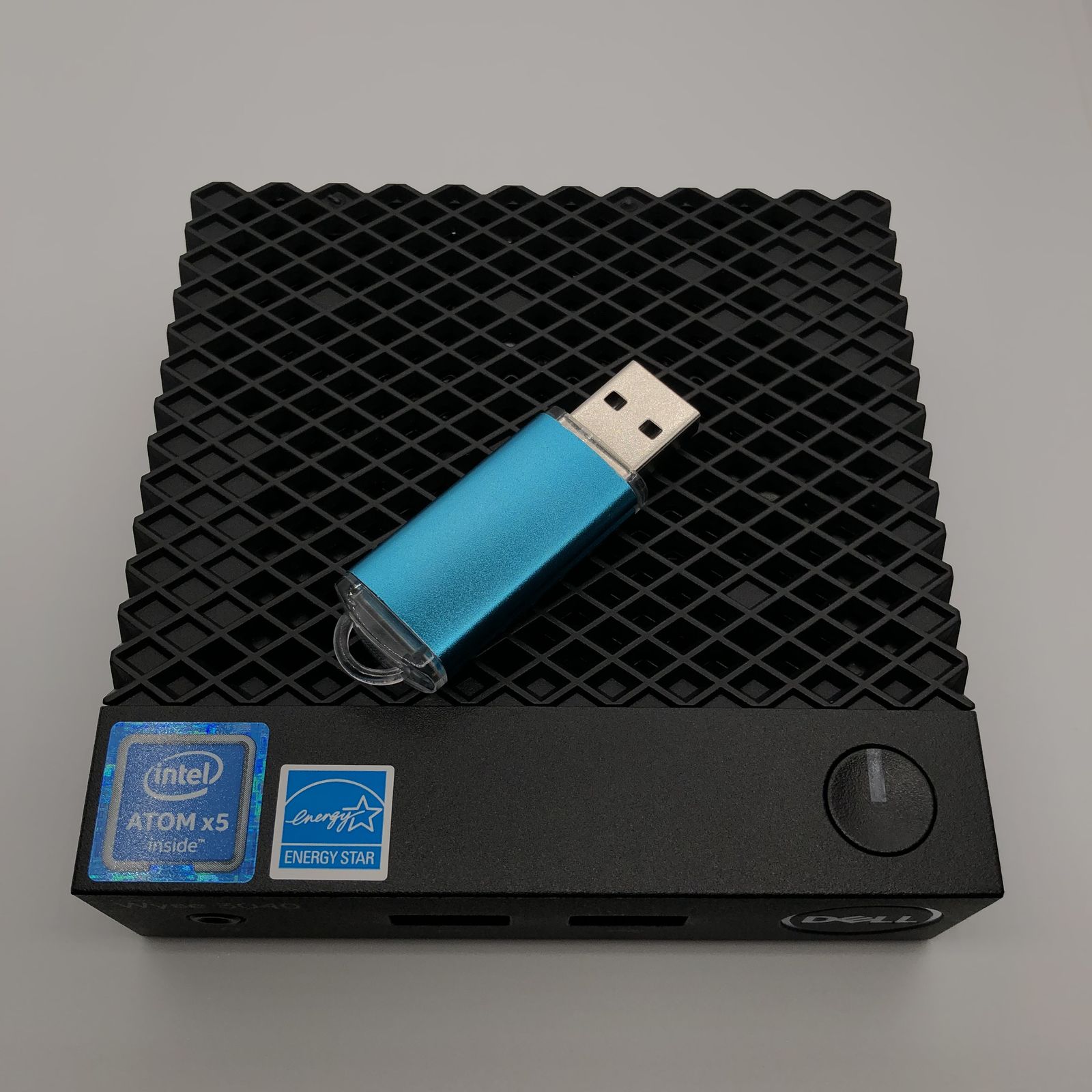
Recently I purchased a couple of used Cisco Meraki MR33 access points to upgrade my wireless network. Up until this point, most of my network equipment was still on 5GHz 802.11n 2x2 (300Mbps). While being sufficient for internet browsing, it really slows down local file transfers. One day I saw someone was selling decommissioned Cisco Meraki APs at pretty reasonable prices, and some research revealed this particular model is even supported in upstream OpenWrt. It turns out riptidewave93 has done some excellent work on bringing OpenWrt support to this device, and even produced detailed flashing instructions. Quick glances at the guide revealed that Cisco later locked down the device with a firmware update and removed the u-boot shell access entirely. This wasn’t so much of a big deal to me because someone posted an NAND dump in the thread discussing this locked u-boot, so even if the device I received have locked bootloaders, I could simply take off the NAND flash and reprogram it offline.
Some people might question the value of going through so much trouble just to get some functional wireless APs, and it’s a perfectly valid concern. Doing this would be a total waste of time for people whose time is worth significantly more than the price of a couple of wireless APs. However, I do have some free time at my disposal, and tinkering with embedded Linux systems is something I personally find fun and rewarding. Plus it’s rather difficult to find cheap consumer grade APs that have this kind of good build quality, support PoE, look nice and clean on the wall, and are available to me at heavily discounted prices. Moreover, this device has three Wi-Fi radios and a BLE radio. The extra Wi-Fi radio could be very useful for keeping old devices incompatible with WPA3 connected, without me having to keep WPA2 on the main radios indefinitely. The BLE radio is potentially useful for IoT, but I haven’t planned to do anything with it just yet.
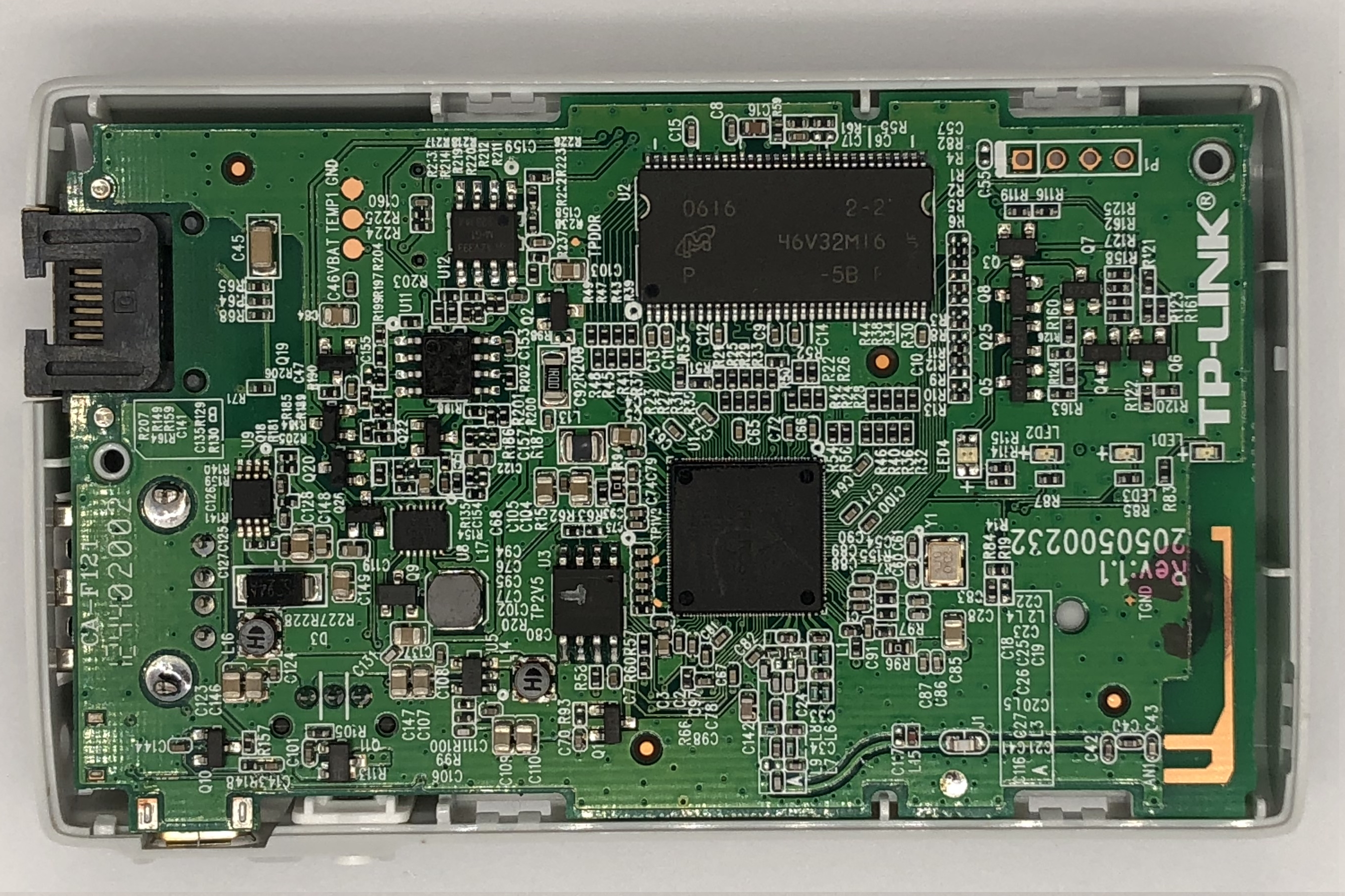
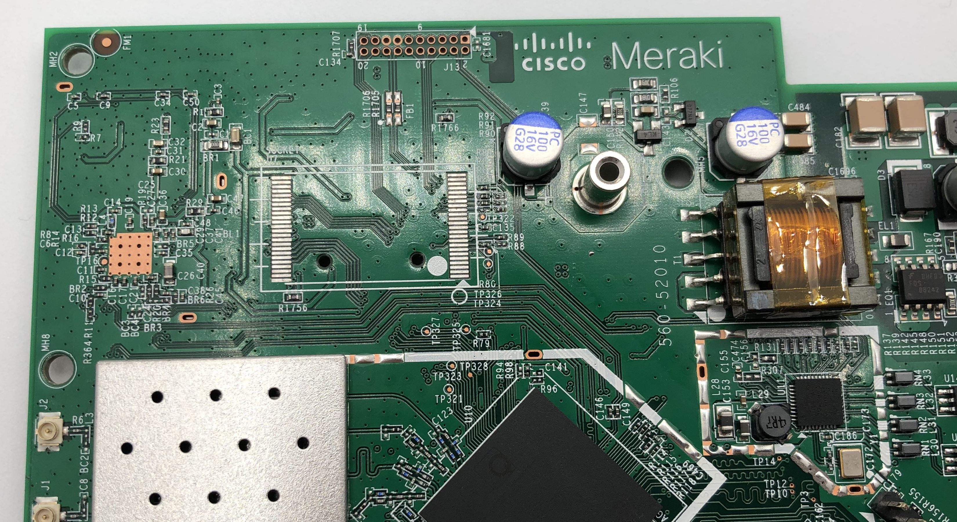
Disassembling this device was fairly simple. Removing the four Torx T5 screws under the four rubber feet and some gentle prying was all I needed to remove the back cover.
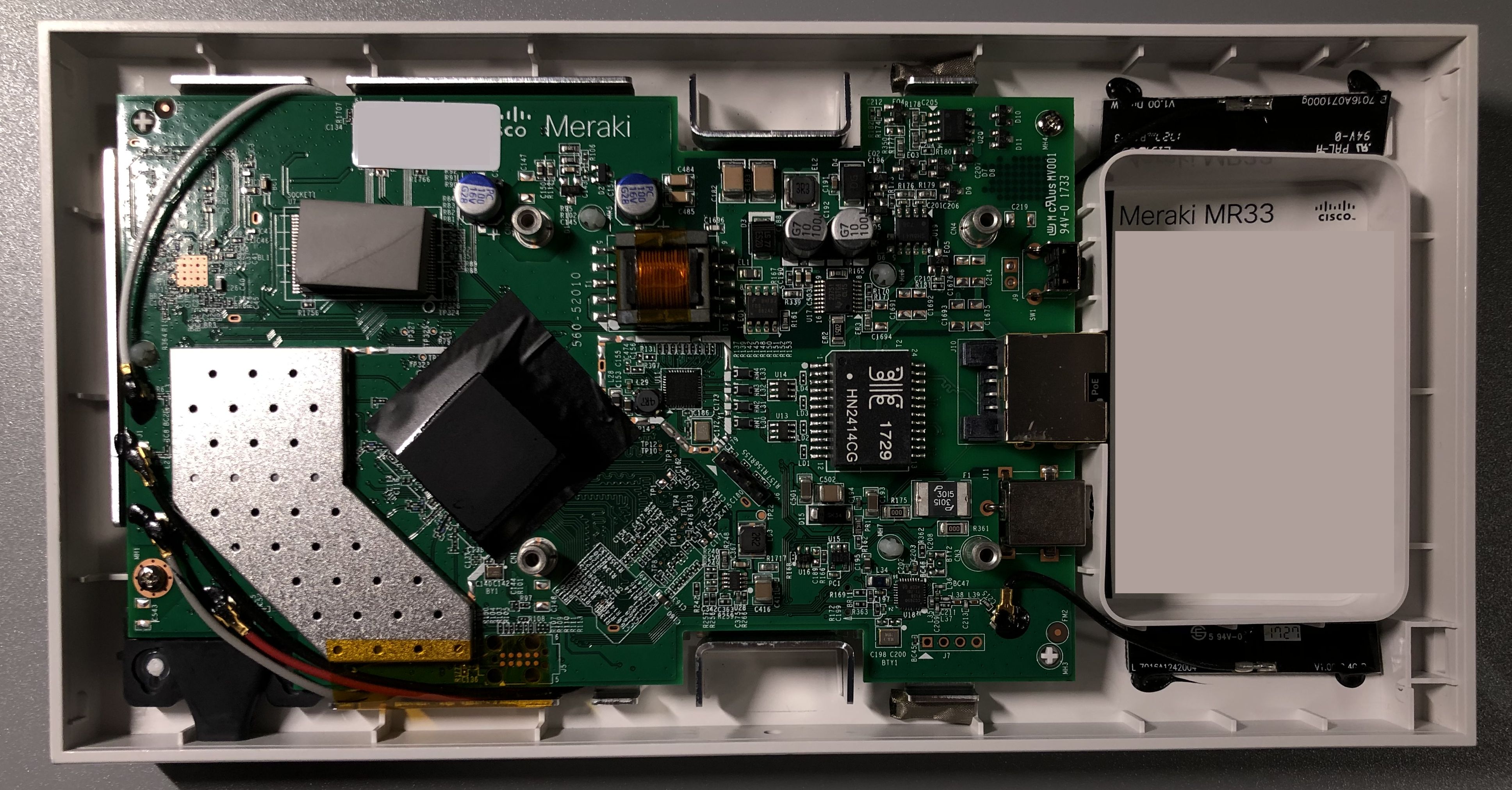
The first MR33 I opened was a jackpot, because it still had the original unlocked U-Boot 2012.07-g97ab7f1 [local,local] (Oct 06 2016 - 13:07:25)
. The device must have been decommissioned for quite a while now, or it would have been automatically updated already. I won’t go through the flashing process just yet because it’s identical to the next one after bootloader replacement. Other than the problem I had with ubootwrite
(which I will talk about below), it was smooth sailing. I backed up all the partitions and installed OpenWrt, and all was well.
Unfortunately, my luck ran out on the second device, and it had the locked U-Boot 2017.07-RELEASE-g78ed34f31579 (Sep 29 2017 - 07:43:44 -0700)
. The xyzzy
escape sequence is no longer working, and the discussion thread on GitHub indicated the entire shell has been removed.
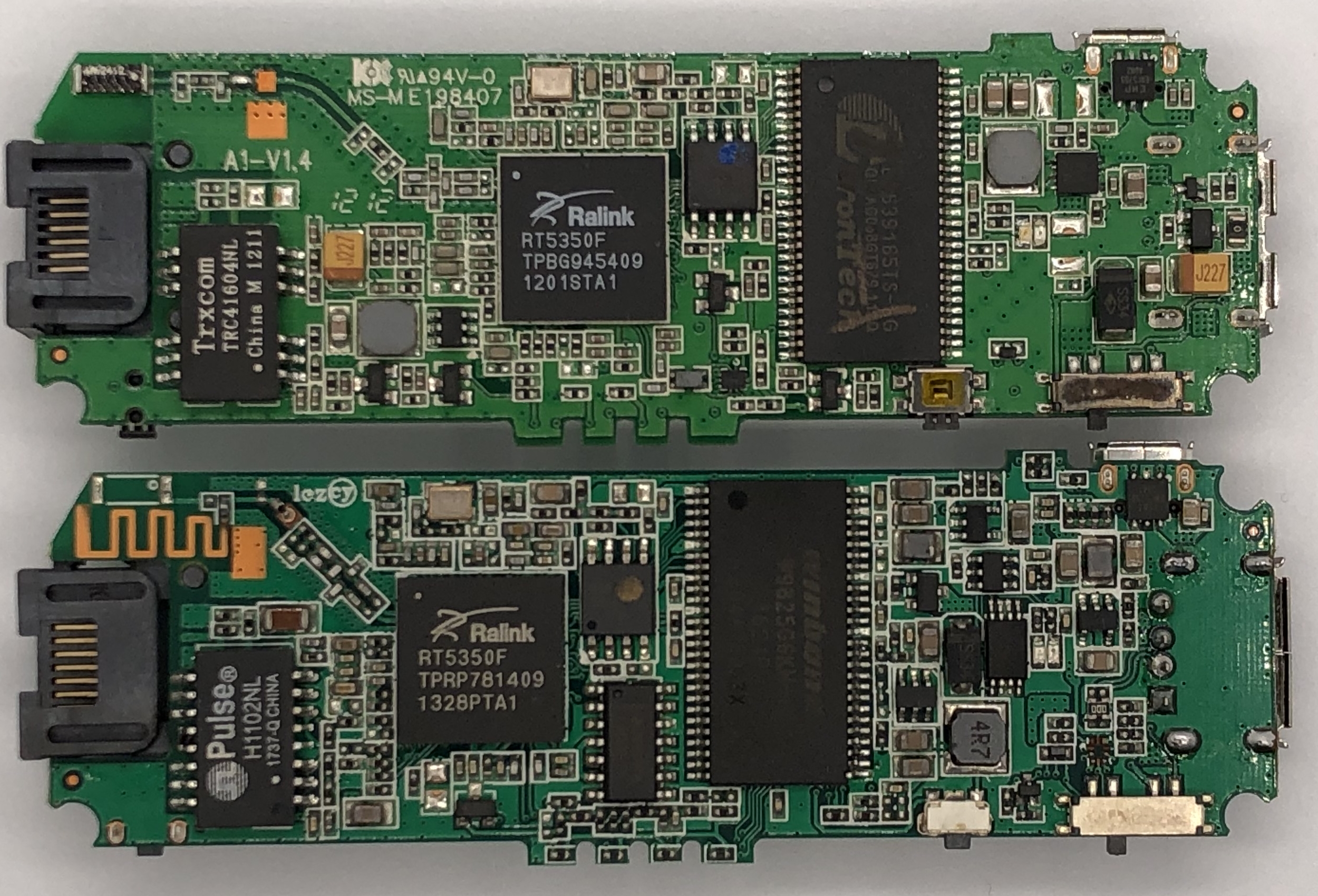
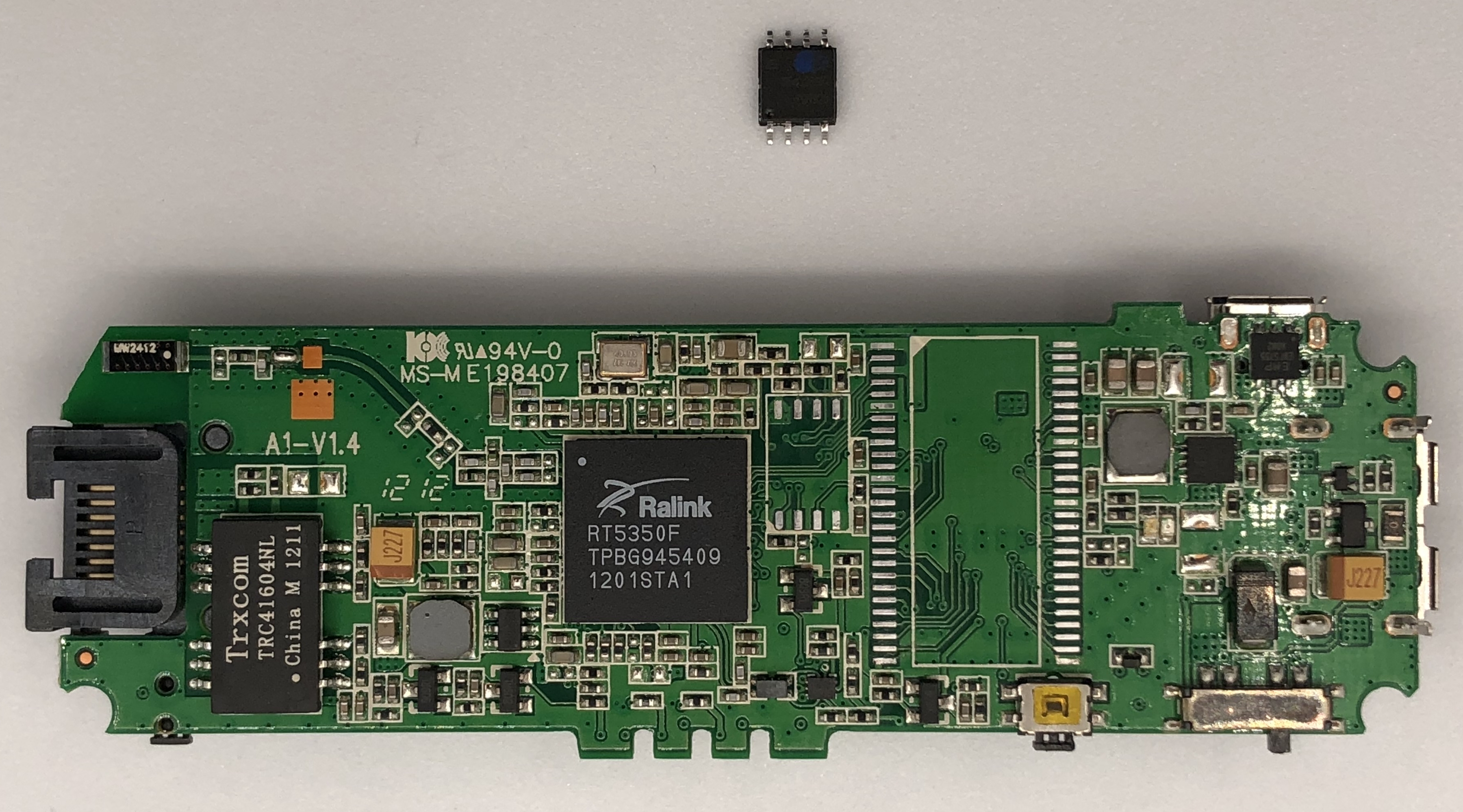
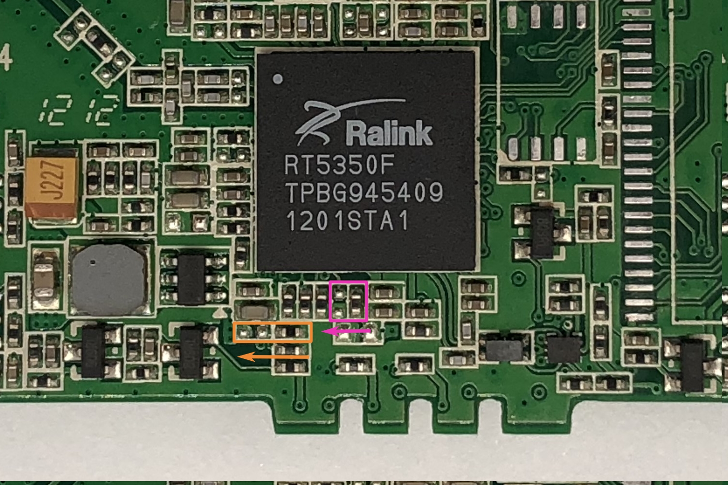
However, I was still wondering if the device would drop back into a shell if boot fails, because sometimes it’s possible to obtain a shell without even knowing the secret escape sequence by simply shorting out the data pins of the flash to make u-boot fail to load the kernel image. Generally speaking, shorting the IO pins with each other on the flash should not have any harmful effects, but it will successfully prevent the host from reading any valid data from the chip. I simply shorted pin 29 and pin 30 with some tweezers.
The idea here is to short the data pins immediately after u-boot starts and before it has a chance to read the kernel image from the NAND. This requires some precision timing and took me more than 10 tries to get it to work, because the NAND is pretty fast and the process of reading a tiny kernel image to memory is almost instant. Unfortunately this did not produce any meaningful results, and someone mentioned in the thread that there’s a possibility of blowing efuses by giving the board random input, so I gave up on this and decided to just pull the flash instead.
U-Boot 2017.07-RELEASE-g78ed34f31579 (Sep 29 2017 - 07:43:44 -0700)
DRAM: 242 MiB
machid : 0x8010001
Product: meraki_Stinkbug
NAND: ONFI device found
ID = 1d80f101
Vendor = 1
Device = f1
128 MiB
Using default environment
In: serial
Out: serial
Err: serial
machid: 8010001
ubi0: attaching mtd1
Nand Flash error. Status = 12336
NAND page read failed. page: 1800 status ffffffb6
Nand Flash error. Status = 12336
NAND page read failed. page: 1840 status ffffffb6
--------< huge flood of errors removed >--------
Nand Flash error. Status = 12336
NAND page read failed. page: fd80 status ffffffb6
Nand Flash error. Status = 12336
NAND page read failed. page: fdc0 status ffffffb6
ubi0: scanning is finished
UBI init error 22
Error, no UBI device/partition selected!
Wrong Image Format for bootm command
ERROR: can't get kernel image!
Error, no UBI device/partition selected!
Wrong Image Format for bootm command
ERROR: can't get kernel image!
resetting ...
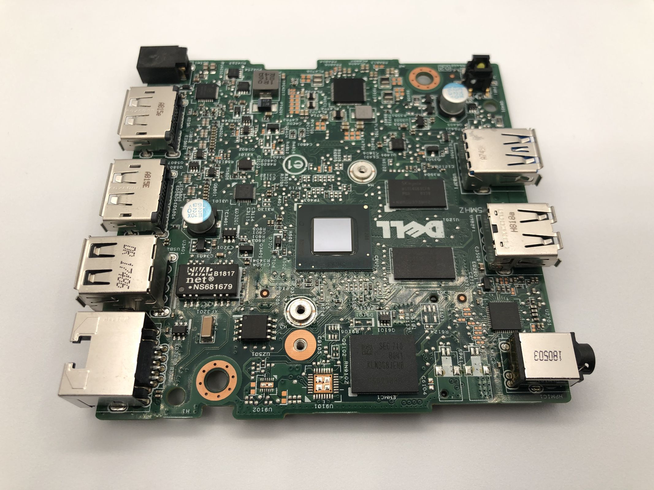
In the GitHub discussion thread, people mentioned a couple of potential solutions, but they all seem to require either manually messing with OOB data and/or expensive specialty devices such as the 360-clip and usbjtag, both of which costs significantly more than what I got my MR33 for, so those are obviously not feasible for me. However, one particular reply stood out to me, because they seem to have reprogrammed the flash with an i.MX 6ULL based Linux board. This is very intriguing for me, as not only does Linux have userspace utilities to read/write raw NAND, u-boot can do that too, and I don’t even have to deal with OOB/ECC data manually anymore. Messing with mtd and devicetree setups won’t be necessary if I could get hold of some other embedded device that can boot from a different medium and read/write the NAND.
I was able to dig up another IPQ40xx based board that happens to boot from SPI NOR but loads its kernel and rootfs from a TSOP48 NAND. Cross compiling a usable copy of functional u-boot for this board was a rather painful process, but I’ll talk about that in a future post.
I am well aware that not everyone just has random dev boards lying around, and this solution might be even less practical/financially viable for most people than buying the 360-clip and a compatible programmer. This post is not meant to be a general tutorial, it’s more like an elaborate journal that I put out in hope it could be an interesting read for people who are interested in the process.
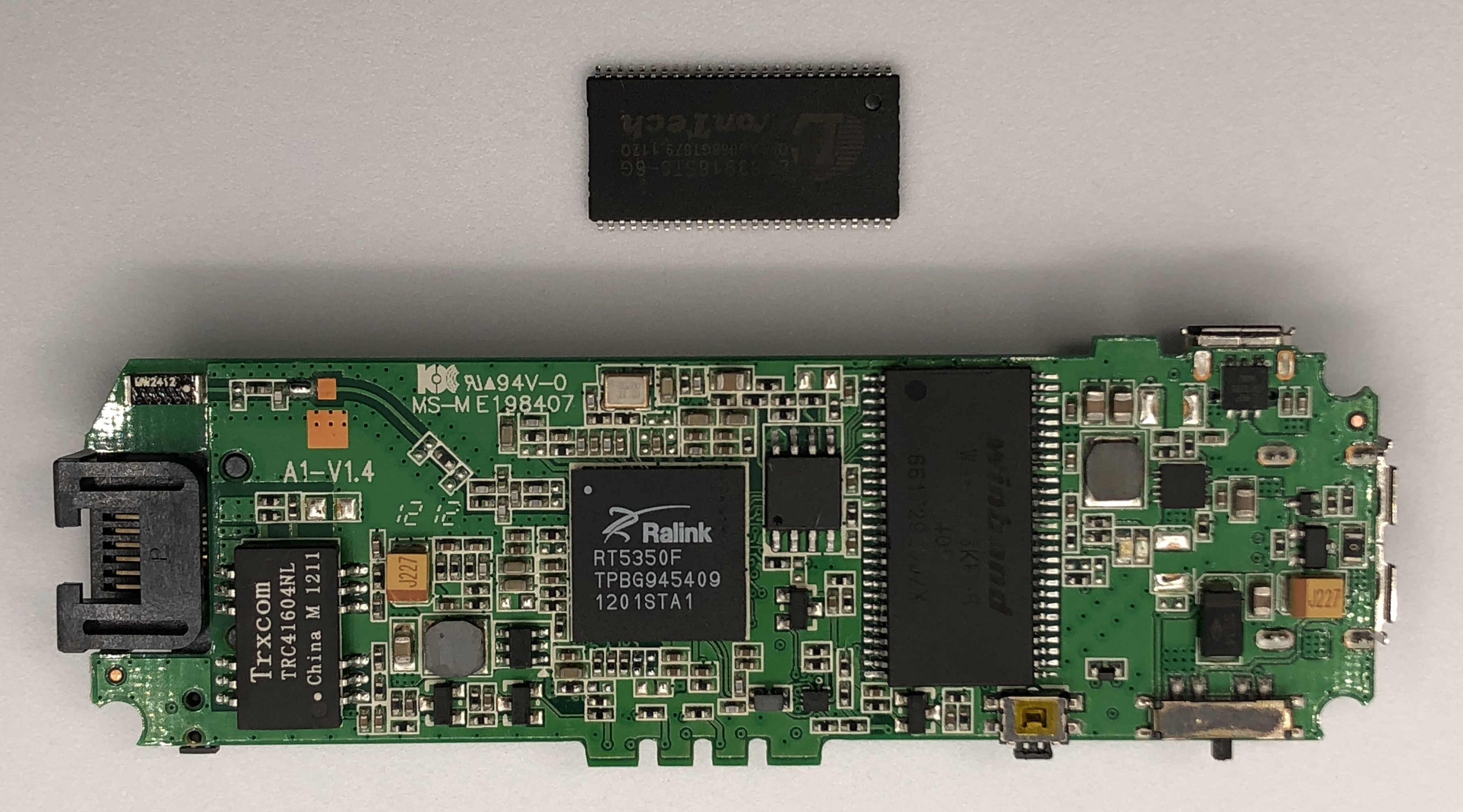
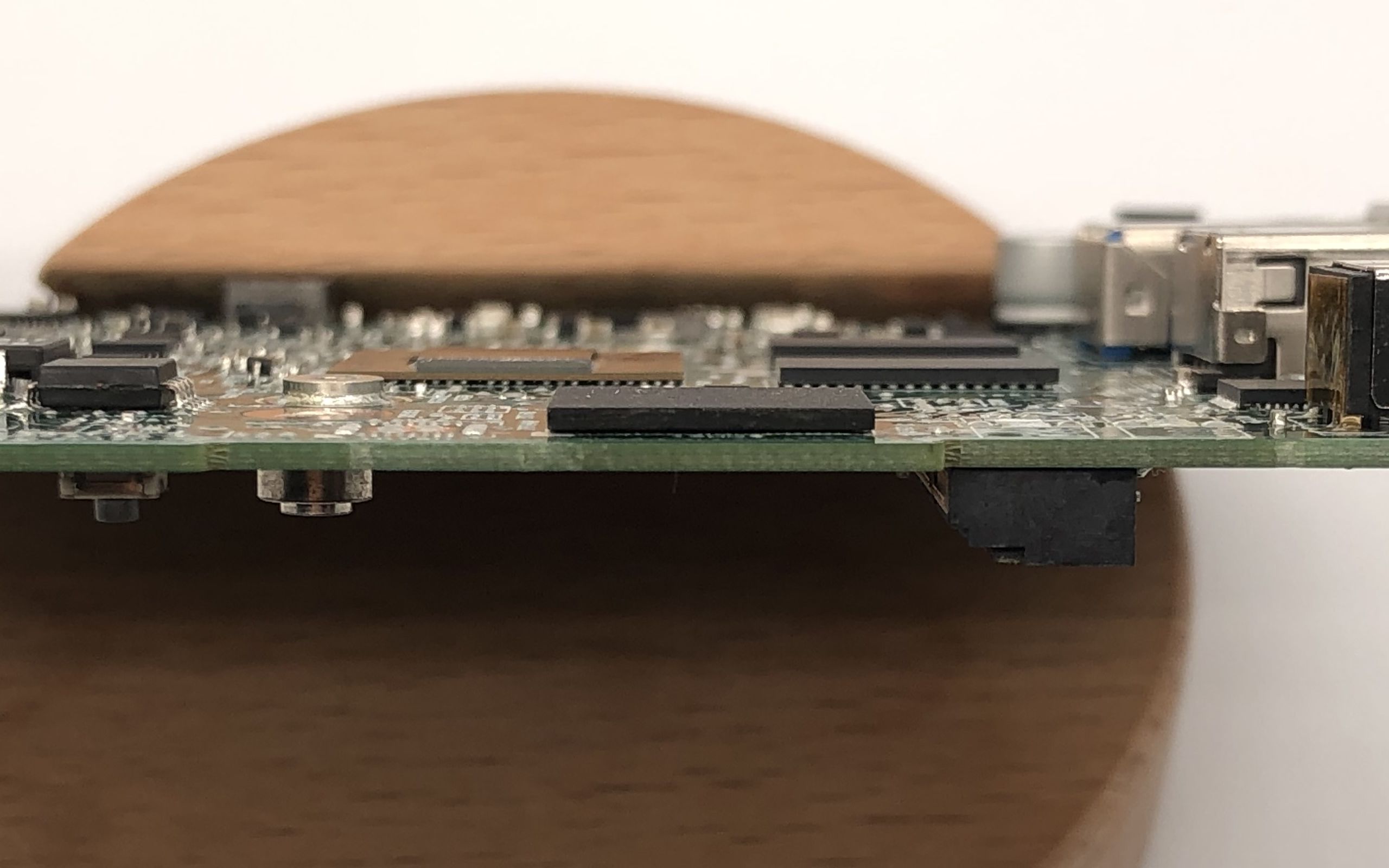
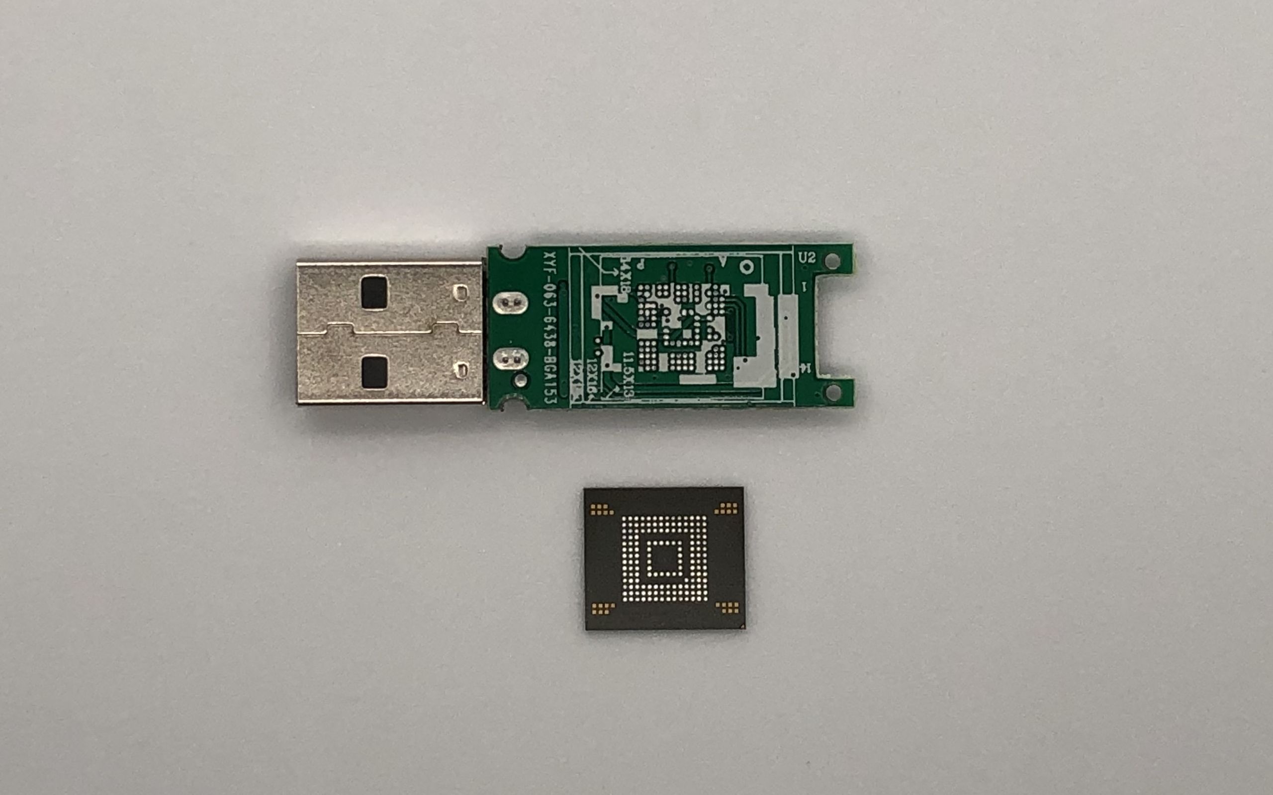
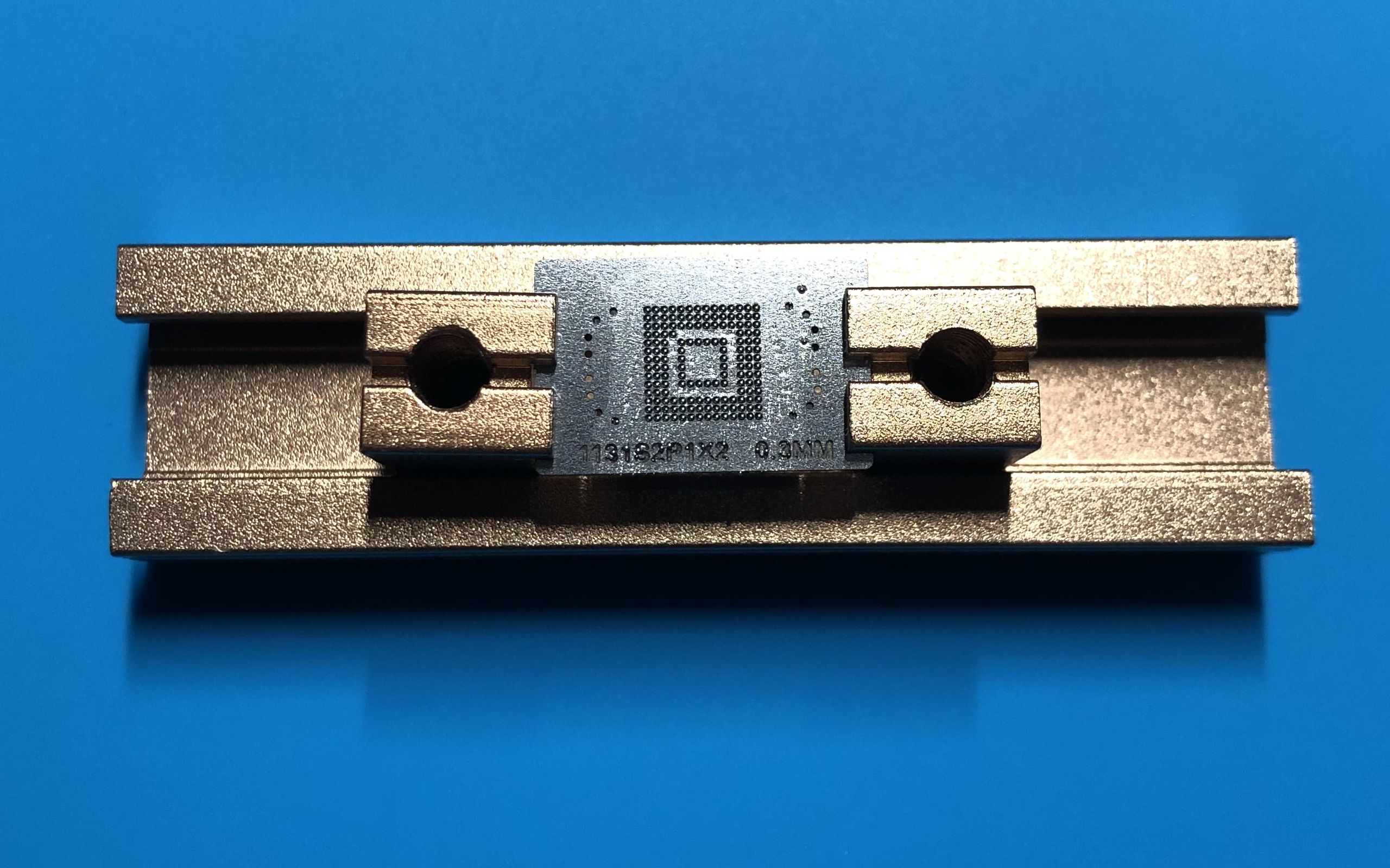
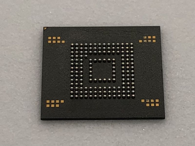
Pulling the flash from the MR33 was a relatively trivial process, but some preheating is still required. A good trick to desolder components on these type of boards with lots and lots of ground planes is to put a decent amount of bismuth solder on the solder joints you’re working with. Bismuth solder has a very low melting point at about 138C, so it will significantly lower the melting point of the lead-free solder onboard when they’re mixed, and the board will become much easier to work with. Not only that, bismuth solder also has a benefit of being lead-free as well. I was able to pull the chip off with my hot air station set to only about 300C. If this was just the lead-free solder, I’d probably have to crank the temperature up to 360C to reliably melt the solder, which is rather dangerous to the board.
The original NAND on the dev board was desoldered and replaced with two 24 pin ZIF connectors.
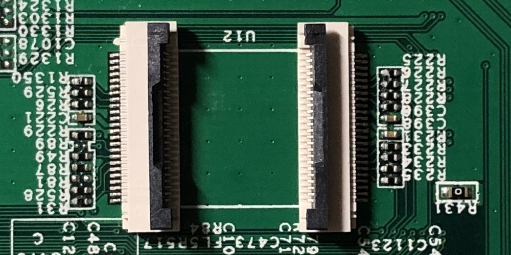
A friend of mine designed a TSOP48 socket adapter board last year, and it finally came in handy this time. This board simply makes a pin to pin connection from the ZIF connectors to the NAND socket, and has no other components onboard.
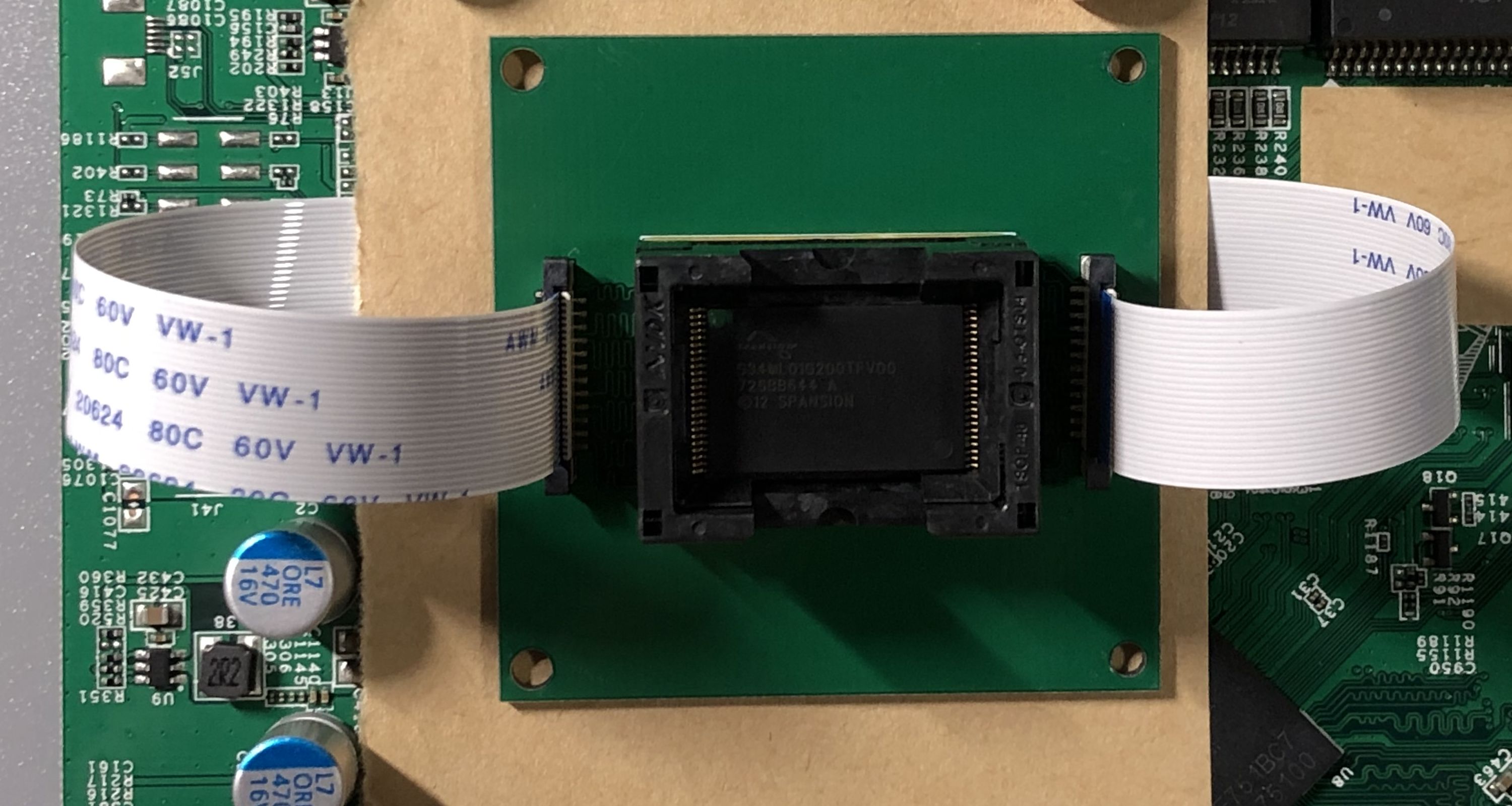
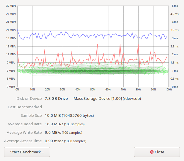
With the flash attached, I powered up the board and backed up the full flash by reading 32MB chunks and sending them to a local TFTP server. The 32MB limit has something to do with the memory map, and it’s out of my control. Loading 64MB of data starting from 0x84000000 (the default load address) would cause a prefetch abort
and a reset because it’s writing to illegal addresses. I did not experiment with pushing the address forward to load more data into memory in one go, because I was uncertain if I would write into memory regions that are already in use.
(IPQ40xx) # nand read 0x84000000 0x0 0x2000000 && tftpput 0x84000000 0x2000000 32M-1.bin
NAND read: device 0 offset 0x0, size 0x2000000
33554432 bytes read: OK
eth0 PHY0 Down Speed :10 Half duplex
eth0 PHY1 up Speed :1000 Full duplex
eth0 PHY2 Down Speed :10 Half duplex
eth0 PHY3 Down Speed :10 Half duplex
eth0 PHY4 Down Speed :10 Half duplex
Using eth0 device
TFTP to server 192.168.1.1; our IP address is 192.168.1.2
Filename '32M-1.bin'.
Save address: 0x84000000
Save size: 0x2000000
Saving: ################################################################
#################################################################
--------< excessive logs removed >--------
######################################################T ###########
###########
done
Bytes transferred = 33554432 (2000000 hex)
(IPQ40xx) # nand read 0x84000000 0x2000000 0x2000000 && tftpput 0x84000000 0x2000000 32M-2.bin
(IPQ40xx) # nand read 0x84000000 0x4000000 0x2000000 && tftpput 0x84000000 0x2000000 32M-3.bin
(IPQ40xx) # nand read 0x84000000 0x6000000 0x2000000 && tftpput 0x84000000 0x2000000 32M-4.bin
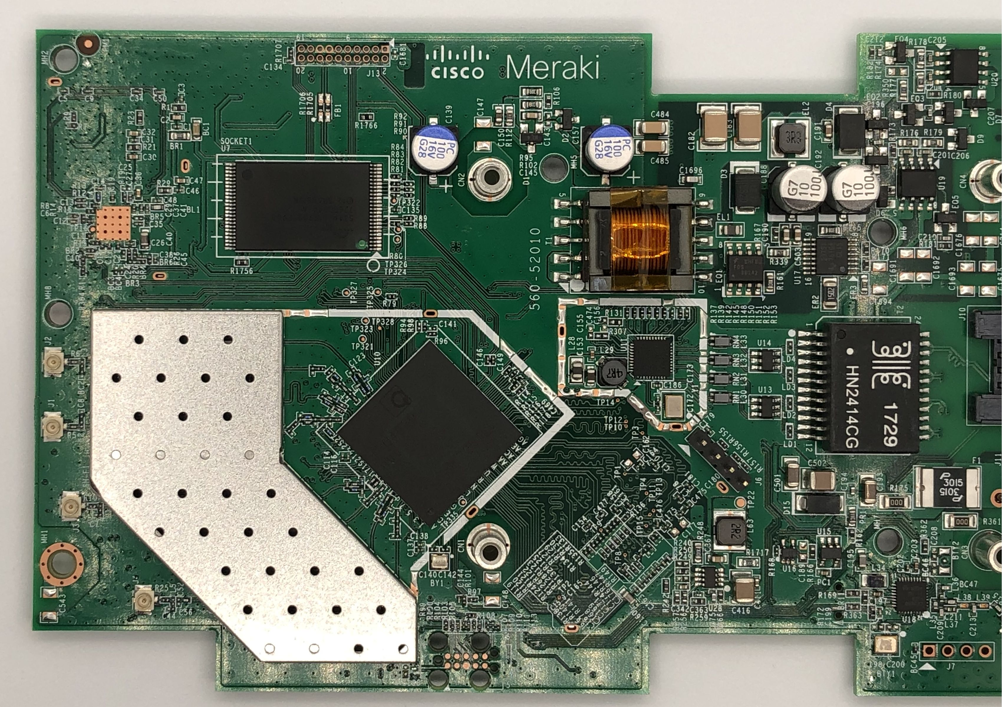
After backing up the flash contents, I read mtd8
on my first MR33 that is already running OpenWrt. mtd8
is the partition named u-boot
here, or more traditionally named APPSBL
by Qualcomm’s terminology.
[ 0.917813] 12 fixed-partitions partitions found on MTD device qcom_nand.0
[ 0.925132] Creating 12 MTD partitions on "qcom_nand.0":
[ 0.931985] 0x000000000000-0x000000100000 : "sbl1"
[ 0.938898] 0x000000100000-0x000000200000 : "mibib"
[ 0.943425] 0x000000200000-0x000000300000 : "bootconfig"
[ 0.948131] 0x000000300000-0x000000400000 : "qsee"
[ 0.953745] 0x000000400000-0x000000500000 : "qsee_alt"
[ 0.958302] 0x000000500000-0x000000580000 : "cdt"
[ 0.963075] 0x000000580000-0x000000600000 : "cdt_alt"
[ 0.967812] 0x000000600000-0x000000680000 : "ddrparams"
[ 0.972890] 0x000000700000-0x000000900000 : "u-boot"
[ 0.979043] 0x000000900000-0x000000b00000 : "u-boot-backup"
[ 0.984316] 0x000000b00000-0x000000b80000 : "ART"
[ 0.988376] 0x000000c00000-0x000007c00000 : "ubi"
I cut up the flash dump from both devices and compared all the partitions except the ubi one, it turns out only u-boot
(APPSBL) was ever updated. Everything else stayed the same.
$ for i in {0..9}; do diff -s mtd$i ../OLD_UBOOT_NAND_BACKUP/nanddump/mtd$i; done
Files mtd0 and ../OLD_UBOOT_NAND_BACKUP/nanddump/mtd0 are identical
Files mtd1 and ../OLD_UBOOT_NAND_BACKUP/nanddump/mtd1 are identical
Files mtd2 and ../OLD_UBOOT_NAND_BACKUP/nanddump/mtd2 are identical
Files mtd3 and ../OLD_UBOOT_NAND_BACKUP/nanddump/mtd3 are identical
Files mtd4 and ../OLD_UBOOT_NAND_BACKUP/nanddump/mtd4 are identical
Files mtd5 and ../OLD_UBOOT_NAND_BACKUP/nanddump/mtd5 are identical
Files mtd6 and ../OLD_UBOOT_NAND_BACKUP/nanddump/mtd6 are identical
Files mtd7 and ../OLD_UBOOT_NAND_BACKUP/nanddump/mtd7 are identical
Binary files mtd8 and ../OLD_UBOOT_NAND_BACKUP/nanddump/mtd8 differ
Files mtd9 and ../OLD_UBOOT_NAND_BACKUP/nanddump/mtd9 are identical
u-boot-backup
remaining the same is rather unexpected, so I did a hexdump of the file and quickly understood why: it’s completely unused.
$ hexdump -C mtd9
00000000 ff ff ff ff ff ff ff ff ff ff ff ff ff ff ff ff |................|
*
00200000
The u-boot image read from the first device was placed on my TFTP server and then loaded into memory of the dev board. The region starting with 0x700000 of size 0x200000 was erased, then the old u-boot image fetched from TFTP was written to the NAND.
(IPQ40xx) # tftpboot mtd8
eth0 PHY0 Down Speed :10 Half duplex
eth0 PHY1 Down Speed :10 Half duplex
eth0 PHY2 Down Speed :10 Half duplex
eth0 PHY3 Down Speed :10 Half duplex
eth0 PHY4 up Speed :1000 Full duplex
Using eth0 device
TFTP from server 192.168.1.1; our IP address is 192.168.1.2
Filename 'mtd8'.
Load address: 0x84000000
Loading: #################################################################
#################################################################
#############
done
Bytes transferred = 2097152 (200000 hex)
(IPQ40xx) # nand erase 0x700000 0x200000
NAND erase: device 0 offset 0x700000, size 0x200000
Erasing at 0x8e0000 -- 100% complete.
OK
(IPQ40xx) # nand write 0x84000000 0x700000 0x200000
NAND write: device 0 offset 0x700000, size 0x200000
2097152 bytes written: OK
After the NAND is programmed, it was soldered back onto the board, and the board was cleaned.
I powered up the board with the serial console attached and saw the familiar U-Boot 2012.07-g97ab7f1 [local,local] (Oct 06 2016 - 13:07:25)
version string. Now the difficult part is finally over, all I needed to do was repeating the steps I went through with the first device.
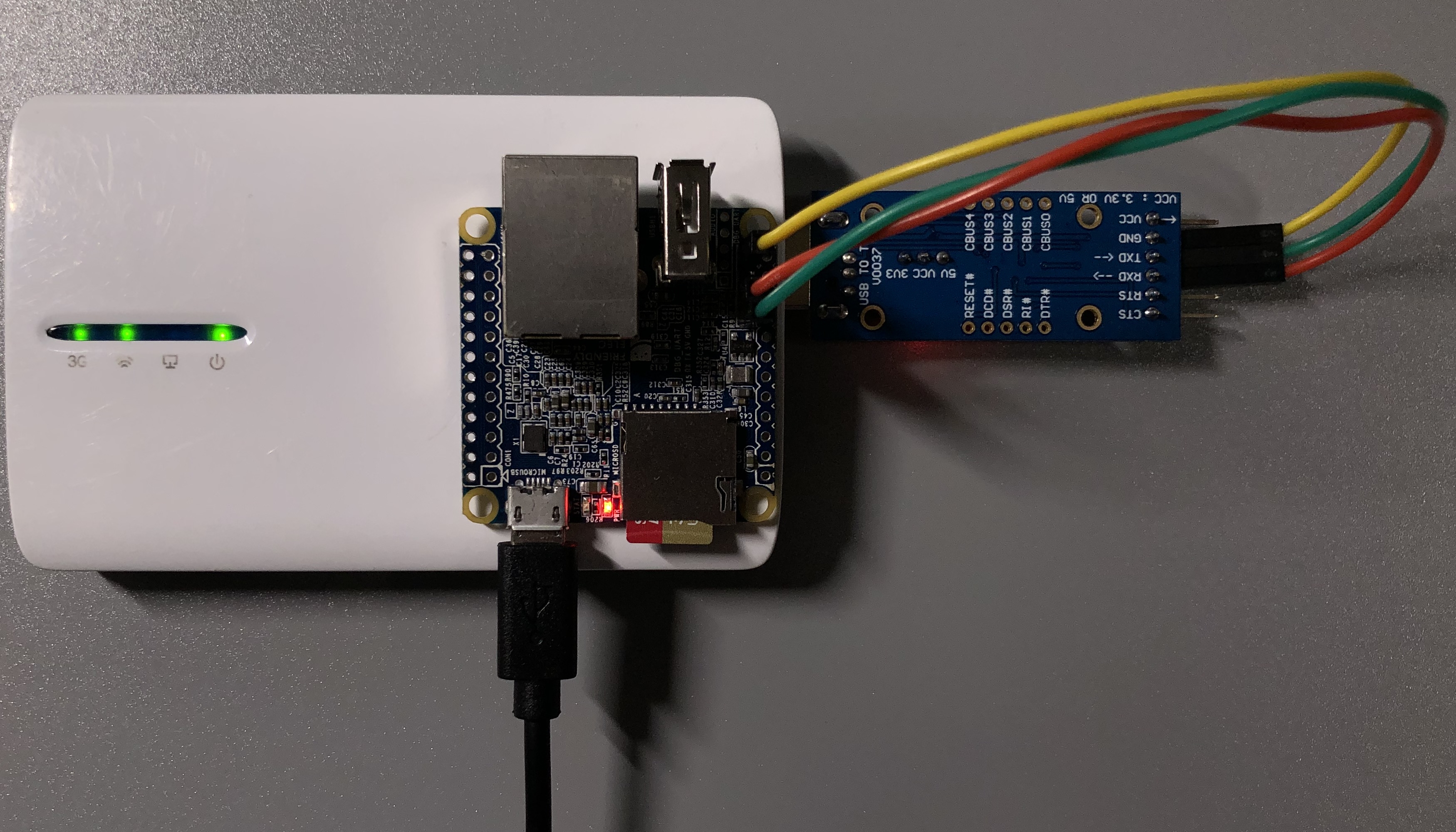
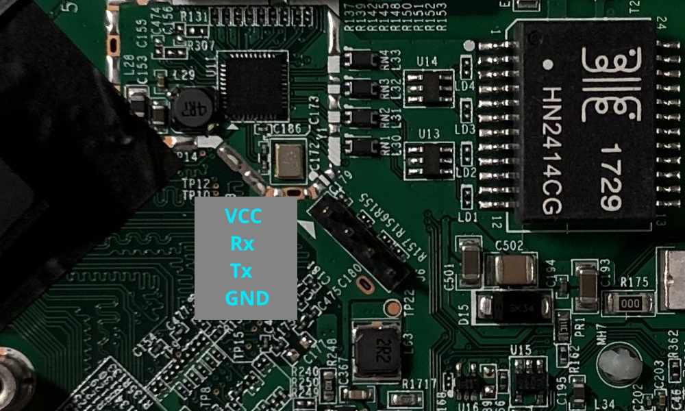
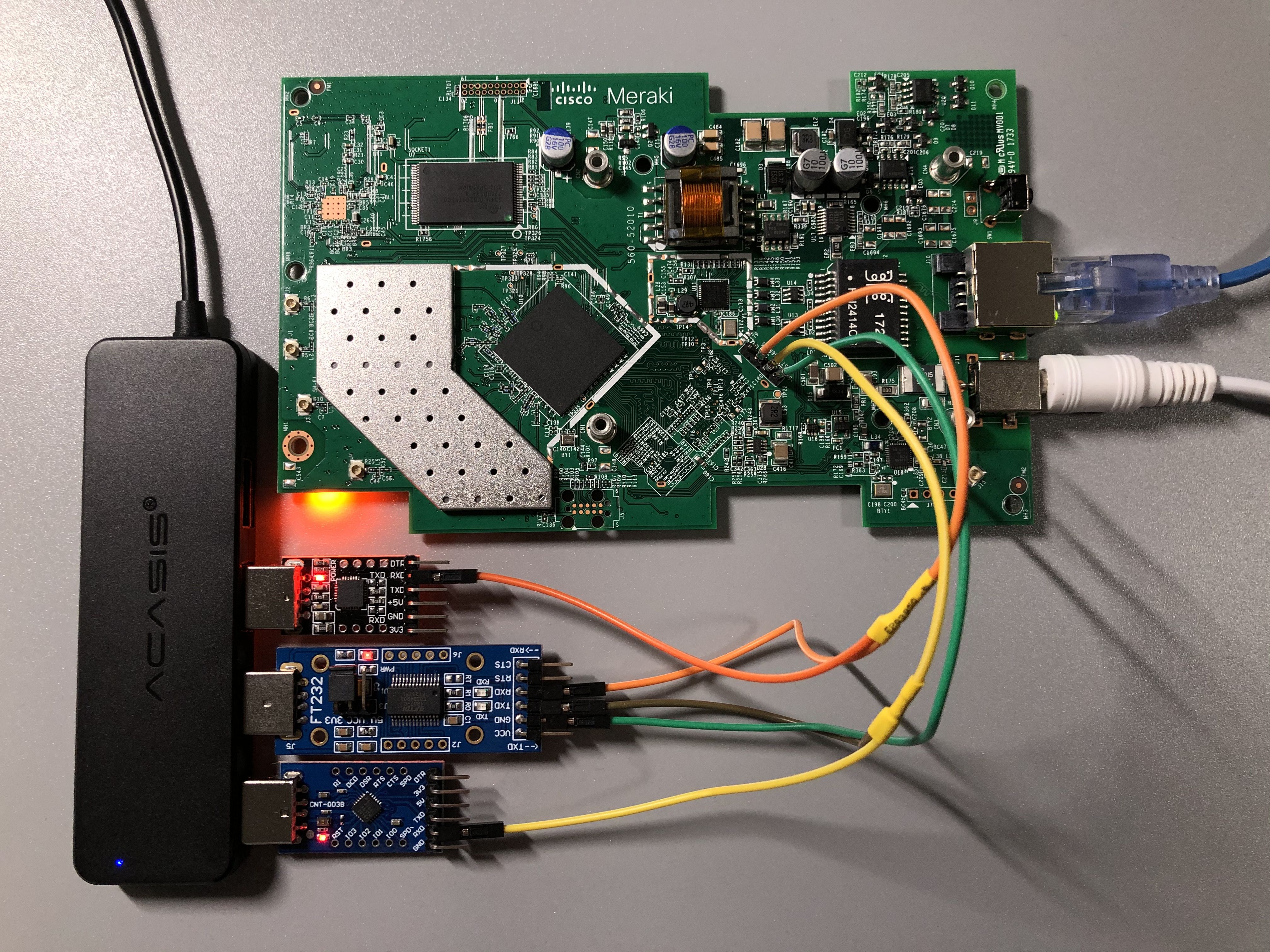
This was actually the tricky part for me personally, mostly caused by some bad assumptions of mine. I totally didn’t realize riptidewave93’s version of ubootwrite
was modified until having spent about half an hour messing with the original version of this script. In hindsight, I should have checked if the script contained the string xyzzy
first. While trying to debug issues with the python script, I found not having any way to watch the serial console really inconvenient, so I came with this setup with three USB serial adapters. One is the main adapter that is used to communicate with the board, and the other two enable me to monitor what’s being sent and received on the Tx and Rx lines.
Do not connect the VCC pin to your serial adapter.
Leaving the antennas detached is more or less fine and probably won’t damage the RF circuitry in this case. Stock OpenWrt will never start transmitting anything with the radios by default, and I will certainly not enable the radios without connecting the antennas first. I recommend connecting all antennas back before powering up the board just to be safe.
The second problem I encountered was with python2.7. Since python2.7 is already EoL, people have started removing it from software repositories. The python2.7 interpreter itself is still widely available for compatibility reasons, but a lot of Linux distributions have already removed most, if not all python2.7 library packages and the python2.7 version of pip
from their repositories. This means installing python-serial
(the python2 flavor of pyserial) is now very difficult. I really didn’t want to use yet another Ubuntu 18.04 virtual machine for this, so I decided to get it from Nixpkgs.
Nix is really convenient for setting up this type of ad-hoc development environments, where I just need a couple of things in a disposable environment to test some other stuff with on occasions, without installing them in a system level package manager.
The latest 21.05 channel on nixpkgs does not have python2.7 packages anymore, so I had to add the older 20.09 channel to get python2.7 related packages.
nix-channel --add https://nixos.org/channels/nixos-20.09
With the channel added, I put these in my shell.nix
, and ran nix-shell
. Now I have the python2.7 version of pyserial, and can proceed with the flashing process.
{ pkgs ? import <nixos-20.09>
{ }
}:
pkgs.mkShell {
nativeBuildInputs = [
python27Packages.pyserial
];
}
Within the newly launched shell, I ran python2 ubootwrite.py --write=mr33-uboot.bin --verbose --serial=/dev/ttyUSB0
and started uploading the intermediary u-boot over serial. This is what the serial consoles look like:
After a couple of minutes of waiting, the intermediate u-boot is started, and I could finally proceed to the next step.
Progress 100%
Waiting for prompt...
Prompt '
STINKBUG # ' not received. Instead received '
## Booting '
COM: kernel from Legacy Image at 82000000 ...
Image Name: MR33-UBOOT-1
Image Type: ARM Linux Kernel Image (gzip compressed)
Data Size: 171744 Bytes = 167.7 KiB
Load Address: 86000000
Entry Point: 86000000
Verifying Checksum ... O
COM: K
Uncompressing Kernel Image ...
COM: OK
Using machid 0x8010001 from environment
Starting kernel ...
The last problem I had was with TFTP. There is a pretty comprehensive rant on this subject which is worth a read in my opinion. However, it’s not like I’ve got any other options, so TFTP it is. Hosting a temporary TFTP file server on Linux is surprisingly annoying, because some of the solutions I tried either require some tedious configuration process, or just flat out did not work. On Windows, there is the excellent tftpd64 project, but unfortunately there doesn’t seem to be anything similar to it on Linux. The solution that finally worked for me was py3tftp, as I was able to put up a functional TFTP server serving the current working directory by simply running sudo py3tftp -v -p 69
.
Actively uploading the OpenWrt ramdisk image to the intermediary u-boot was much less painful, echo -e "binary\nput openwrt-19.07.6-ipq40xx-generic-meraki_mr33-initramfs-fit-uImage.itb" | tftp 192.168.1.1
seems to work just fine. I didn’t use the supplied image but opted to use an official stable build instead. Additionally, I was unaware of the existence of OpenWrt 19.07.7 back when I was flashing the device, or I would have used that instead.
After more waiting, I finally got into OpenWrt.
Starting kernel ...
[ 0.000000] Booting Linux on physical CPU 0x0
[ 0.000000] Linux version 4.14.215 (builder@buildhost) (gcc version 7.5.0 (OpenWrt GCC 7.5.0 r11278-8055e38794)) #0 SMP Tue Jan 19 13:10:02 2021
Installing OpenWrt to the NAND is a rather trivial process. Since the entire NAND was imaged in the previous chapter, basically all that is required is to delete all UBI volumes except ART (radio calibration data), re-create the fail-safe partition with an OpenWrt ramdisk boot image, and performing a normal sysupgrade. The rest of the volumes will be automatically recreated by sysupgrade and all the free space I have freed by deleting old useless volumes from the Meraki firmware will be available to OpenWrt.
# Cleaning up old UBI volumes used by the factory firmware
root@OpenWrt:/# ubinfo -a | grep -e "Volume ID" -e "Size" -e "Name"
Volume ID: 0 (on ubi0)
Size: 137 LEBs (17395712 bytes, 16.5 MiB)
Name: diagnostic1
Volume ID: 1 (on ubi0)
Size: 133 LEBs (16887808 bytes, 16.1 MiB)
Name: storage
Volume ID: 4 (on ubi0)
Size: 80 LEBs (10158080 bytes, 9.6 MiB)
Name: part.safe
Volume ID: 5 (on ubi0)
Size: 67 LEBs (8507392 bytes, 8.1 MiB)
Name: rootfs-25-xxxxxxxxxxxxxxxxxxxxxxxxxxx
Volume ID: 6 (on ubi0)
Size: 5 LEBs (634880 bytes, 620.0 KiB)
Name: ART
Volume ID: 7 (on ubi0)
Size: 19 LEBs (2412544 bytes, 2.3 MiB)
Name: part.old
root@OpenWrt:/# ubirmvol /dev/ubi0 -n 0
root@OpenWrt:/# ubirmvol /dev/ubi0 -n 1
root@OpenWrt:/# ubirmvol /dev/ubi0 -n 4
root@OpenWrt:/# ubirmvol /dev/ubi0 -n 5
root@OpenWrt:/# ubirmvol /dev/ubi0 -n 7
root@OpenWrt:/# ubinfo -a | grep -e "Volume ID" -e "Size" -e "Name"
Volume ID: 6 (on ubi0)
Size: 5 LEBs (634880 bytes, 620.0 KiB)
Name: ART
# The following files were transferred to /tmp over scp
# openwrt-19.07.6-ipq40xx-generic-meraki_mr33-initramfs-fit-uImage.itb
# openwrt-19.07.6-ipq40xx-generic-meraki_mr33-squashfs-sysupgrade.bin
# Recreating the failsafe UBI volume and writing the OpenWrt ramdisk boot image to it
root@OpenWrt:/# file="/tmp/openwrt-19.07.6-ipq40xx-generic-meraki_mr33-initramfs-fit-uImage.itb"
root@OpenWrt:/# size=$(cat "$file" | wc -c)
root@OpenWrt:/# ubimkvol /dev/ubi0 --size=$size --type=static --name=part.old
Volume ID 0, size 53 LEBs (6729728 bytes, 6.4 MiB), LEB size 126976 bytes (124.0 KiB), static, name "part.old", alignment 1
root@OpenWrt:/# ubiupdatevol /dev/ubi0_0 "$file"
root@OpenWrt:/# ubinfo -a | grep -e "Volume ID" -e "Size" -e "Name"
Volume ID: 0 (on ubi0)
Size: 53 LEBs (6729728 bytes, 6.4 MiB)
Name: part.old
Volume ID: 6 (on ubi0)
Size: 5 LEBs (634880 bytes, 620.0 KiB)
Name: ART
# Performing a normal sysupgrade
root@OpenWrt:/# sysupgrade -v /tmp/openwrt-19.07.6-ipq40xx-generic-meraki_mr33-squashfs-sysupgrade.bin
Cannot save config while running from ramdisk.
Commencing upgrade. Closing all shell sessions.
Watchdog handover: fd=3
- watchdog -
killall: telnetd: no process killed
Sending TERM to remaining processes ... netifd odhcpd uhttpd ntpd ubusd dnsmasq urngd logd rpcd
Sending KILL to remaining processes ...
Performing system upgrade...
Volume ID 1, size 23 LEBs (2920448 bytes, 2.7 MiB), LEB size 126976 bytes (124.0 KiB), dynamic, name "part.safe", alignment 1
Volume ID 2, size 25 LEBs (3174400 bytes, 3.0 MiB), LEB size 126976 bytes (124.0 KiB), dynamic, name "rootfs", alignment 1
Set volume size to 97263616
Volume ID 3, size 766 LEBs (97263616 bytes, 92.7 MiB), LEB size 126976 bytes (124.0 KiB), dynamic, name "rootfs_data", alignment 1
sysupgrade successful
Now OpenWrt has been successfully installed to the NAND, and all the space I freed up is available to the system. There are some size discrepancies with the above output, because this is taken from a device running a more recent image built by myself, with some more things added on top.
root@OpenWrt:~# df -h
Filesystem Size Used Available Use% Mounted on
/dev/root 3.8M 3.8M 0 100% /rom
tmpfs 121.4M 224.0K 121.2M 0% /tmp
/dev/ubi0_3 82.5M 60.0K 78.2M 0% /overlay
overlayfs:/overlay 82.5M 60.0K 78.2M 0% /
tmpfs 512.0K 0 512.0K 0% /dev
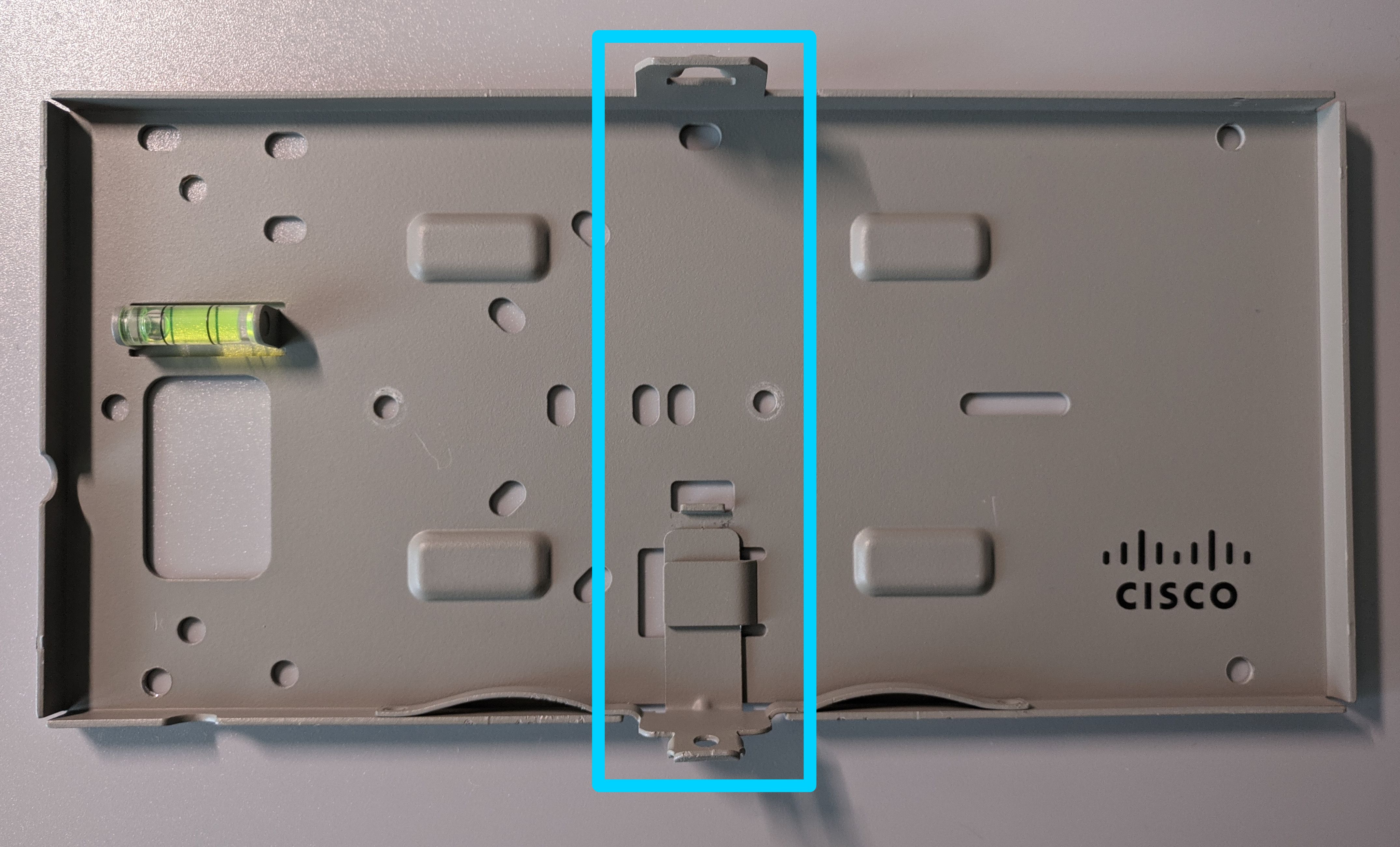
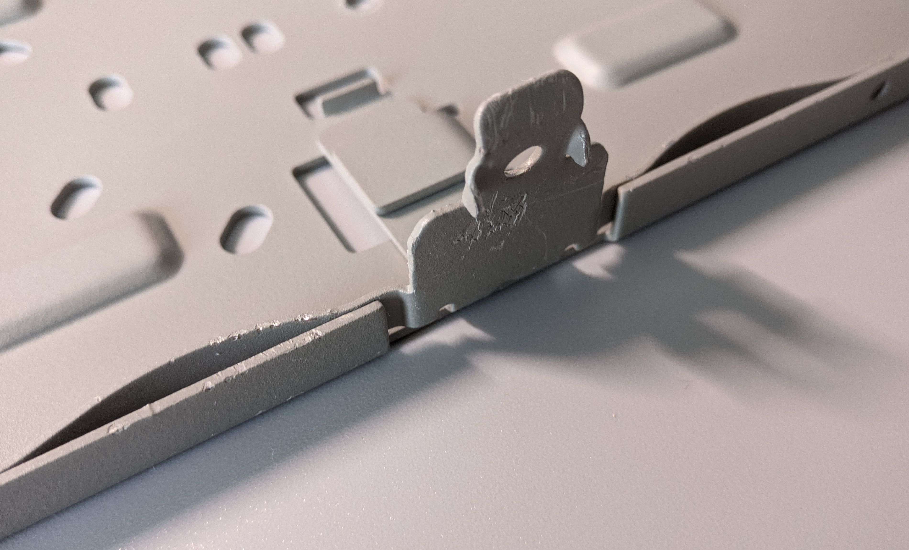
With the software side properly taken care of, now I need to find a way to wall-mount these. Unfortunately, only one of the MR33s came with the factory mounting bracket. The essential part of this bracket is pretty much just the highlighted section. Additionally, the hooks on the spring-loaded section can be omitted as well, since a security screw will be used.
So I took some rough measurements with a caliper and traced a rough shape in OpenSCAD:
difference() {
polygon([[0,0],[0,137],[4.95,137],[4.95,140],[14.65,140],[14.65,137],[19.6,137],[19.6,0]], paths=[[0,1,2,3,4,5,6,7,8]]);
}
This PNG illustration below is not perfectly to scale, it’s for dimension reference only. If you wish to send this to someone to cut it for you, please render the above source code in OpenSCAD and do a proper export from there.
The file exported from OpenSCAD was then sent to a metal laser cutting company. This is cut from 1.5mm aluminum sheets, which is just barely bendable by hand with pliers, and somewhat of an overkill for mounting such a lightweight AP. The bend job I did with pliers was pretty terrible, but that’s all I could do without a proper bench vice. In any case, this won’t be visible once the AP is mounted anyway, so it’s not a big deal. The screw holes were not included in the OpenSCAD source, because hand bending can cause a lot of variations, and it’s very unlikely that the wall-mount screw holes will be centered, and it’s even more unlikely that the security screw hole will be properly aligned at all. It’s best to bend it, fit it onto the AP, tighten the security screw a little to leave a mark on the bracket, and then drill a hole at that mark.
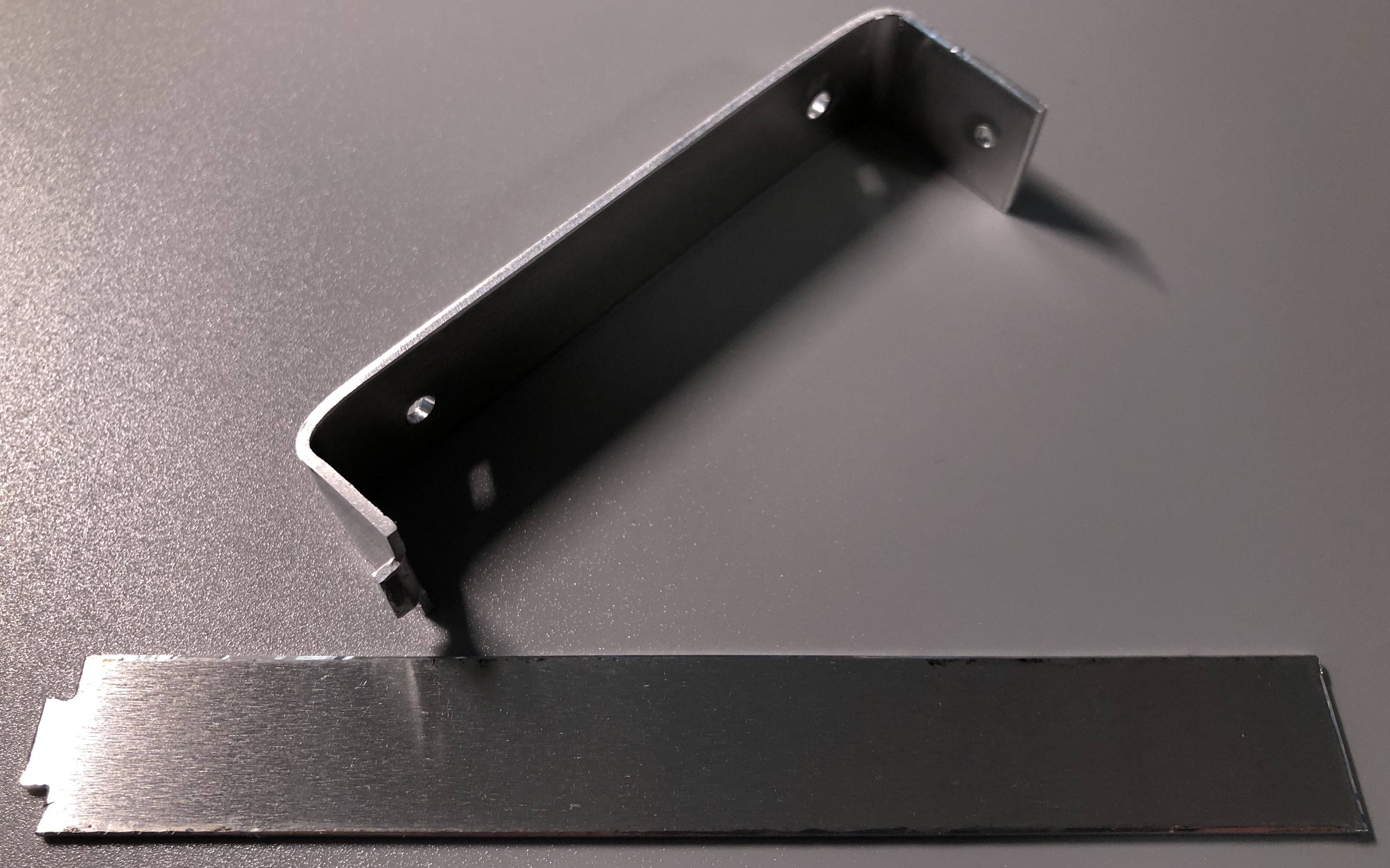
I placed a rubber foot near the top side of the bracket to keep the AP from tilting towards the wall.
About the security screw, it’s DIN7991, 2.5mm in diameter, and 12mm in length.
Flashing this device was unnecessarily complicated, but I learned quite a bit from this experience. Plus seeing all these decommissioned devices brought back to life with open-source firmware is a rather rewarding process. While the practice of aggressively locking down devices is really annoying from a tinkerer’s perspective, since this device is still officially supported by Cisco until 2026, it sadly does not make any financial sense for them to allow people to unlock the hardware and avoid the subscription service entirely.
Unfortunately, Cisco does not send out firmware updates to unlock devices after they are EoL, so without access to soldering tools and special NAND programmers, they will all end up as e-waste for most people. Perhaps it won’t matter much after 2026 since they will be long obsolete, but honestly I was still using 802.11n equipment up until now, so I can totally see myself using 802.11ac equipment few years down the line. Thanks to OpenWrt, most of the new CVEs related to Wi-Fi on the AP side can be patched or at least mitigated without having to change equipment.
]]>This post is reconstructed from notes written in early February back when most of the work on the project happened, so the information might be slightly out of date. A decent amount of effort was made in keeping this information up to date, and firmware builds have been re-tested at the time of writing to ensure they all work as intended.
Serial console is one of the most important ways of communicating with embedded Linux systems. I’ve used a lot of USB serial adapters over the years, but they all seem to have two major drawbacks that are difficult to overcome:
They are not electrically isolated. Whenever the target board is powered up, there is always a small chance that a power surge will happen due to ground loop interference, which causes my connection to be interrupted on power-up:
FATAL: read zero bytes from port
term_exitfunc: reset failed for dev UNKNOWN: Input/output error
By the time I could reconnect with my terminal software (picocom
in this case), I would have already missed a lot of critical messages printed by the bootloader. This makes diagnosing and debugging bootloader related problems very unpleasant. To make matters worse, should something bad happens to my board and a high voltage was sent to the tx/rx pins, it can potentially go back to my computer and destroy my PCH, since EHCI/XHCI controllers are typically integrated in the PCH nowadays.
The UART cable length limit makes it difficult to work with on a messy desk, as a USB hub or at least an extension cable would always be required, further contributing to the clutter, and the bare PCBs have risks of being accidentally shorted out by my other metallic tools if not careful.
While talking to some network engineers, I found that some people had Wi-Fi or BLE based wireless console adapters, which allow them to access the RS-232 serial consoles wirelessly. Some research later, a series of products called Airconsole from Cloudstore Limited perked my interests. From the looks of it, most of their Wi-Fi enabled options look extremely similar to a series of older “3G router” products manufactured by HAME. The Mini model looks almost identical to MPR-A5, the Std/Pro one looks almost identical to MPR-A1, and the XL looks almost identical to MPR-A2. These HAME models are later cloned by other manufacturers and then sold as generic products, and they can still be found to this day on places such as eBay and AliExpress.
With this information in mind, I figured it’s easier for me to make my own wireless serial console adapter with some of the old portable routers I have lying around. There is no need for Bluetooth connectivity or smartphone apps for me personally, all I want is something that I can connect to locally and lets me interact with a serial console over a secure connection. Transport security is highly desirable because having my login credentials transmitted in plaintext is highly undesirable, even on my own LAN.
After some consideration, I have decided running picocom
over an SSH session, on a battery powered OpenWrt device would be the easiest to implement for me. SSH is the best option for me because the “trust on first use” design has a much lower setup overhead compared to a traditional PKI based TLS/HTTPS setup, while still remaining secure. OpenWrt offers an easy-to-use configuration web interface for setting up the Wi-Fi connection, has (mostly) up to date userspace software, and is pretty much the only Linux distribution that will work on these routers anyway.
Here are some alternatives solutions and ideas that were considered in my research, and why they were not selected for this project:
dropbear
is already provided by OpenWrt by default feels very redundant.With the context out of the way, some hardware upgrades are required for me to be able to fit modern OpenWrt onto these devices in my possession. The TP-Link TL-MR11U only has 4MB of NOR flash and 32MB of DRAM. While 32MB is sufficient for what I’m going to run, 4MB is not enough to store the required software anymore. The HAME MPR-A1 only has 4MB of NOR flash and 16MB of DRAM, neither of which are sufficient for anything I need.
The MPR-A1 and the MPR-A2 are almost identical devices aside from having less storage, memory and a smaller battery. In fact OpenWrt builds for A2 will work on the A1 if you upgrade its NOR flash and DRAM. I’ll be putting in 8MB of NOR flash and 32MB of DRAM to match the MPR-A2. Disassembling the MPR-A1 was fairly straightforward, so no photos were taken during the teardown process.
The new NOR flash was not soldered back until I spliced the firmware and wrote the new firmware image to the flash. Board images are all placed here for the sake of better organization.
I just happened to have an MPR-A2 clone, so I thought I’d put the two PCBs together as a comparison too. It’s interesting to see the clone opted for cheaper parts in some places to cut costs. I won’t be working on the clone as it already has 8MB of NOR flash and 32MB of DRAM.
According to the RT5350F’s datasheet, DRAM configuration is either set in EEPROM, or configured externally via two bootstrapping pins. In MPR-A1’s case, it’s configured via those two bootstrapping pins. Unfortunately, this SoC cannot properly address one single 64MB DRAM chip (only 32MB*2), so 32MB is as good as it gets.
For the MR11U, upgrading is much easier, since the bootloader can auto-detect the DRAM configuration and there are no bootstrapping pins to worry about. The datasheet of the SoC says the maximum supported flash size is 16MB, and the maximum supported DRAM size is 64MB, so that’s what I put in.
I won’t go over the setup process here, the wiki does a pretty good job explaining that. After the source has been cloned, I did the following to build my firmware image:
# check out the v19.07.7 branch
$ git checkout v19.07.7
# clean, update and force install all package feeds
# -f is required because some packages won't show up as they contain files that may
# override built-in packages, and this behavior is typically disallowed by default
$ scripts/feeds clean && scripts/feeds update -a && scripts/feeds install -af
This is the configuration that was used for the upgraded MPR-A1. Since I’m borrowing the config for the MPR-A2, no further changes to the source code is required, as the new flash that was put in matches the capacity of the MPR-A2. The change in DRAM will get picked up by the bootloader and passed onto the kernel thanks to the new bootstrapping configuration. On top of the defaults, only ECC and compression support in dropbear
were enabled, and some USB serial drivers, picocom
, shadow-utils (because creating a separate user is desirable) and LuCI (the web configuration interface) were added.
CONFIG_TARGET_ramips=y
CONFIG_TARGET_ramips_rt305x=y
CONFIG_TARGET_ramips_rt305x_DEVICE_mpr-a2=y
CONFIG_DEVEL=y
CONFIG_CCACHE=y
# enable ECC and compression support in dropbear
CONFIG_DROPBEAR_ECC=y
CONFIG_DROPBEAR_ECC_FULL=y
CONFIG_DROPBEAR_ZLIB=y
# enable luci
CONFIG_PACKAGE_luci=y
# USB serial drivers
CONFIG_PACKAGE_kmod-usb-acm=y
CONFIG_PACKAGE_kmod-usb-serial=y
CONFIG_PACKAGE_kmod-usb-serial-ch341=y
CONFIG_PACKAGE_kmod-usb-serial-cp210x=y
CONFIG_PACKAGE_kmod-usb-serial-ftdi=y
CONFIG_PACKAGE_kmod-usb-serial-pl2303=y
# terminal software
CONFIG_PACKAGE_picocom=y
# enable shadow_utils
CONFIG_PACKAGE_shadow-utils=y
After writing these to .config
in the root directory of the source tree, simply running make defconfig
will tell the build system to automatically resolve dependencies and complete the config file.
$ make defconfig
# download all of the required source archives
$ make download -j10
# compile the image, running with a high nice value to avoid stalling other applications on the system
$ nice -n 19 make -j$(nproc)
Unfortunately, the build quickly failed. Running make V=s -j1
revealed the problem originated from build_dir/host/mklibs-0.1.35
, whose makefile is tools/mklibs/Makefile
.
In file included from elf_data.hpp:24,
from elf.cpp:21:
elf.hpp:52:56: error: ISO C++17 does not allow dynamic exception specifications
52 | const section &get_section(unsigned int i) const throw (std::out_of_range) { return *sections.at(i); };
| ^~~~~
elf.hpp:62:47: error: ISO C++17 does not allow dynamic exception specifications
62 | static file *open(const char *filename) throw (std::bad_alloc, std::runtime_error);
| ^~~~~
elf.hpp:65:38: error: ISO C++17 does not allow dynamic exception specifications
65 | file(uint8_t *mem, size_t len) throw (std::bad_alloc) : mem(mem), len(len) { }
| ^~~~~
elf.hpp:68:52: error: ISO C++17 does not allow dynamic exception specifications
68 | static file *open_class(uint8_t *, size_t) throw (std::bad_alloc, std::runtime_error);
| ^~~~~
elf.hpp:131:55: error: ISO C++17 does not allow dynamic exception specifications
131 | std::string get_string(uint32_t offset) const throw (std::bad_alloc)
| ^~~~~
elf.hpp:266:39: error: ISO C++17 does not allow dynamic exception specifications
266 | std::string get_version() const throw (std::bad_alloc);
| ^~~~~
elf.hpp:267:44: error: ISO C++17 does not allow dynamic exception specifications
267 | std::string get_version_file() const throw (std::bad_alloc);
| ^~~~~
elf.hpp:269:44: error: ISO C++17 does not allow dynamic exception specifications
269 | std::string get_name_version() const throw (std::bad_alloc);
| ^~~~~
elf.hpp:308:29: error: ISO C++17 does not allow dynamic exception specifications
308 | version_requirement() throw (std::bad_alloc);
| ^~~~~
----------snip----------
make[7]: *** [Makefile:382: elf.o] Error 1
I checked what the upstream Makefile looks like on 21.02, and it seems like HOST_CPPFLAGS += -std=gnu++98
needs to be set in my makefile. Further inspection reveals that the 0.1.35 version does not even exist on Debian’s server anymore, so I upgraded the version number, archive extension (.xz instead of .gz) and the hash corresponding to v0.1.44 as well.
diff --git a/tools/mklibs/Makefile b/tools/mklibs/Makefile
index 507c2fd394..48b1eace40 100644
--- a/tools/mklibs/Makefile
+++ b/tools/mklibs/Makefile
@@ -7,17 +7,18 @@
include $(TOPDIR)/rules.mk
PKG_NAME:=mklibs
-PKG_VERSION:=0.1.35
+PKG_VERSION:=0.1.44
-PKG_SOURCE:=$(PKG_NAME)_$(PKG_VERSION).tar.gz
+PKG_SOURCE:=$(PKG_NAME)_$(PKG_VERSION).tar.xz
PKG_SOURCE_URL:=http://ftp.de.debian.org/debian/pool/main/m/mklibs/
-PKG_HASH:=ccb1023dc1729c5a37ca6c3eca8e4bac3491116763c8820dfce8eea4845c8567
+PKG_HASH:=3af0b6bd35e5b6fc58d8b68827fbae2ff6b7e20dd2b238ccb9b49d84722066c2
HOST_FIXUP:=autoreconf
include $(INCLUDE_DIR)/host-build.mk
HOST_CFLAGS += -I$(CURDIR)/include
+HOST_CPPFLAGS += -std=gnu++98
define Host/Install
$(INSTALL_BIN) \
After deleting build_dir/host/mklibs-0.1.35
and re-running the build process, everything worked out this time, and a sysupgrade image was generated at bin/targets/ramips/rt305x/openwrt-ramips-rt305x-mpr-a2-squashfs-sysupgrade.bin
. I’ll put that aside for now and compile an image for the TP-Link device.
For the TP-Link TL-MR11U, a little modification to the source is required. The upgraded DRAM does not require any changes since it’s auto-detected by the bootloader and then passed onto the kernel, but for the flash size, I need to change the build target of this device to make sure the 16MB flash layout is selected. For the old ar71xx
target, it’s as simple as changing which macro this device’s definition points to. My hardware revision is v2, but the v2 definition points to v1, so it’s v1 that I would need to change.
diff --git a/target/linux/ar71xx/image/tiny-tp-link.mk b/target/linux/ar71xx/image/tiny-tp-link.mk
index 9612694469..a38df7f5af 100644
--- a/target/linux/ar71xx/image/tiny-tp-link.mk
+++ b/target/linux/ar71xx/image/tiny-tp-link.mk
@@ -13,7 +13,7 @@ endef
TARGET_DEVICES += tl-mr10u-v1
define Device/tl-mr11u-v1
- $(Device/tplink-4mlzma)
+ $(Device/tplink-16mlzma)
DEVICE_TITLE := TP-LINK TL-MR11U v1
DEVICE_PACKAGES := kmod-usb-core kmod-usb2 kmod-usb-ledtrig-usbport
BOARDNAME := TL-MR11U
This is very important for the ar71xx
target, much more important than the previous device, which was rampis
, as I will elaborate in the firmware splicing part below.
Thear71xx
target has now been dropped due to it being mostly replaced by the newer, device-tree basedath79
target. However, not all devices have been ported toath79
.
The configuration is very similar to the previous device:
CONFIG_TARGET_ar71xx=y
CONFIG_TARGET_ar71xx_tiny=y
CONFIG_TARGET_ar71xx_tiny_DEVICE_tl-mr11u-v2=y
CONFIG_DEVEL=y
CONFIG_CCACHE=y
# enable ECC and compression support in dropbear
CONFIG_DROPBEAR_ECC=y
CONFIG_DROPBEAR_ECC_FULL=y
CONFIG_DROPBEAR_ZLIB=y
# enable luci
CONFIG_PACKAGE_luci=y
# USB serial drivers
CONFIG_PACKAGE_kmod-usb-acm=y
CONFIG_PACKAGE_kmod-usb-serial=y
CONFIG_PACKAGE_kmod-usb-serial-ch341=y
CONFIG_PACKAGE_kmod-usb-serial-cp210x=y
CONFIG_PACKAGE_kmod-usb-serial-ftdi=y
CONFIG_PACKAGE_kmod-usb-serial-pl2303=y
# terminal software
CONFIG_PACKAGE_picocom=y
# enable shadow_utils
CONFIG_PACKAGE_shadow-utils=y
Now to build the firmware:
# complete configuration
$ make defconfig
# clean built artifacts
$ make clean
# download all of the required source archives
$ make download -j10
# compile the image, running with a high nice value to avoid stalling other applications on the system
$ nice -n 19 make -j$(nproc)
Now I have the image at bin/targets/ar71xx/tiny/openwrt-ar71xx-tiny-tl-mr11u-v2-squashfs-factory.bin
.
First, both chips I took off from the devices was dumped with my SPI flash programmer and flashrom
. The flash programmer used here is an excellent open-source project: stm32-vserprog. The repository has both hardware and firmware designs. This can read and write chips much faster than the CH341 based programmers, and it’s quite easy to assemble.
These two devices are both MIPS, but that’s pretty much where the similarities end. The firmware setup for these two devices are completely different, so two different appaoches were required to splice things together and put back onto the new NOR flash.
Generally speaking, a wireless router/access point type embedded Linux system like this would have a couple of partitions:
It’s worth noting that wireless calibration data must be preserved, because this is unique on a per-board basis. This is why cross-flashing other people’s full flash dumps as-is is typically not a good idea, because you will end up with subpar RF performance and wrong MAC addresses, not to mention potentially violating FCC (or the local equivalent) regulations, and why it’s always recommended having a full image backup of the flash before tinkering with any devices.
First, I need to cut up the stock firmware dump to individual partition images according to the partition table for use later. This can be simply accomplished with dd if=A1_full_dump.bin of=$PARTITION_NAME bs=1 count=$SIZE_IN_BYTES skip=$START_OFFSET_IN_BYTES
, or simply selecting, copying and pasting data in a hex editor.
partitions {
compatible = "fixed-partitions";
#address-cells = <1>;
#size-cells = <1>;
partition@0 {
label = "u-boot";
reg = <0x0 0x30000>;
read-only;
};
partition@30000 {
label = "u-boot-env";
reg = <0x30000 0x10000>;
read-only;
};
factory: partition@40000 {
label = "factory";
reg = <0x40000 0x10000>;
read-only;
};
partition@50000 {
compatible = "denx,uimage";
label = "firmware";
reg = <0x50000 0x3b0000>;
};
For this SoC, a modified bootloader is also required to make use of the 32MB of DRAM according to old forum posts.
So overall the only two partitions required from the original flash image would be u-boot-env
and factory
. u-boot-env
contains configuration for the bootloader that I don’t need to modify, factory
is the conventional radio calibration data and MAC address storage partition for Ralink (and MediaTek MIPS) devices.
The sysupgrade image generated by the build system is actually a complete uImage directly bootable by the bootloader, with the rootfs squashfs image appended after it. All I needed to do is writing this to 0x50000
of the flash. This sysupgrade file does have some trailing metadata, but these will be automatically erased when the overlay partition is automatically reformatted on first boot, thus it can be safely ignored.
$ file bin/targets/ramips/rt305x/openwrt-ramips-rt305x-mpr-a2-squashfs-sysupgrade.bin
bin/targets/ramips/rt305x/openwrt-ramips-rt305x-mpr-a2-squashfs-sysupgrade.bin: u-boot legacy uImage, Linux Kernel Image, Linux/MIPS, OS Kernel Image (lzma), 1280356 bytes, Mon Feb 15 15:22:37 2021, Load Address: 0x80000000, Entry Point: 0x80000000, Header CRC: 0x2D529961, Data CRC: 0x804D50B5
Now that I have all the data, it’s time to reconstruct a bootable full flash image. While this could have been more convenient to do in a GUI hex editor, it would be easier to explain what’s going on if it was done with dd
. The firmware
partition of MPR-A2 is 0x7b0000
in size instead of 0x3b0000
, but otherwise they have identical flash layouts.
# Take the modified bootloader binary that can use 32MB of DRAM, and generate a padding to pad it to 0x30000 with 0xFF.
$ FILE="uboot256.img" dd if=/dev/zero bs=1 count=$((0x30000 - $(stat --format=%s $FILE))) |tr \\000 \\377 > u-boot_padding
91104+0 records in
91104+0 records out
91104 bytes (91 kB, 89 KiB) copied, 0.0971852 s, 937 kB/s
# Concatenate the padding with the u-boot image
$ cat uboot256.img u-boot_padding > u-boot_partition
# Concatenate the u-boot partiton (now with the correct size), u-boot environment variable partition the wireless calibration data parition together.
$ cat u-boot_partition u-boot-env factory > header
# Generate a padding filled with 0xFF to pad the frimware partiton to the correct size
$ FILE="openwrt-ramips-rt305x-mpr-a2-squashfs-sysupgrade.bin" dd if=/dev/zero bs=1 count=$((0x7b0000 - $(stat --format=%s $FILE))) |tr \\000 \\377 > firmware_padding
3865866+0 records in
3865866+0 records out
3865866 bytes (3.9 MB, 3.7 MiB) copied, 1.49983 s, 2.6 MB/s
# Concatenate the sysupgrade image with the padding
$ cat openwrt-ramips-rt305x-mpr-a2-squashfs-sysupgrade.bin firmware_padding > firmware_partiton
# Concatenate everything together
$ cat header firmware_padding > full.bin
# Write the assembled full image to the new flash chip
$ flashrom -p serprog:dev=/dev/ttyACM1:400000000 -w full.bin
With the chip written, it was soldered back onto the board. After cleaning up the board, it was powered on and the system came up as expected. It took about 3 minutes to fully initialize the jffs2 overlay as it needed to erase everything in the overlay partition. Subsequent normal boots take about 1 minute, while being a little slow, is still an acceptable trade-off for the convenience.
[ 78.870911] jffs2_scan_eraseblock(): End of filesystem marker found at 0x0
[ 78.926935] jffs2_build_filesystem(): unlocking the mtd device...
[ 78.927077] done.
[ 78.943362] jffs2_build_filesystem(): erasing all blocks after the end marker...
[ 80.627250] br-lan: port 1(eth0) entered blocking state
[ 80.652812] br-lan: port 1(eth0) entered disabled state
[ 80.663982] device eth0 entered promiscuous mode
[ 80.838653] br-lan: port 1(eth0) entered blocking state
[ 80.849204] br-lan: port 1(eth0) entered forwarding state
[ 80.860561] IPv6: ADDRCONF(NETDEV_UP): br-lan: link is not ready
[ 82.058579] IPv6: ADDRCONF(NETDEV_CHANGE): br-lan: link becomes ready
[ 177.313272] done.
[ 177.317307] jffs2: notice: (1135) jffs2_build_xattr_subsystem: complete building xattr subsystem, 0 of xdatum (0 unchecked, 0 orphan) and 0 of xref (0 dead, 0 orphan) found.
[ 177.746829] overlayfs: upper fs does not support tmpfile.
This device requires a different approach. Since the factory bootloader can auto-detect the 64MB of DRAM that was put in, and I can simply apply openwrt-ar71xx-tiny-tl-mr11u-v2-squashfs-factory.bin
from the stock TP-Link firmware, all it would be required was mirroring the ART
(Atheros Radio Test, wireless calibration data) partition to where it should be on a 16MB device. On these Atheros based devices, ART
is commonly simply located in the last 64KB of the flash, and this device is no exception.
Doing this one with dd
would be slightly more difficult than the previous one and would require more messy arithmetic operations, so I didn’t bother with this one and simply used a hex editor to do the job. Basically, the gist is:
After the 16MB OpenWrt image was flashed onto the device, it will automatically pick up the new ART
data which was placed at the end of the new 16MB flash. Now all I need to do was writing this image to the new 16MB chip and soldering it back to the board.
# Write the assembled full image to the new flash chip
$ flashrom -p serprog:dev=/dev/ttyACM1:400000000 -w full.bin
This board came up and finished erasing the overlay slightly faster than the other device, only taking a little over 2 minutes to initialize the overlay. Just like the previous device, normal boots take about 1 minute, while being a little slow, is still an acceptable trade-off for the convenience.
[ 90.206076] jffs2_scan_eraseblock(): End of filesystem marker found at 0x0
[ 90.211744] jffs2_build_filesystem(): unlocking the mtd device...
[ 90.211818] done.
[ 90.219575] jffs2_build_filesystem(): erasing all blocks after the end marker...
[ 90.859188] br-lan: port 1(eth0) entered blocking state
[ 90.870509] br-lan: port 1(eth0) entered disabled state
[ 90.876126] device eth0 entered promiscuous mode
[ 90.927039] IPv6: ADDRCONF(NETDEV_UP): br-lan: link is not ready
[ 94.978202] eth0: link up (100Mbps/Full duplex)
[ 94.981345] br-lan: port 1(eth0) entered blocking state
[ 94.986506] br-lan: port 1(eth0) entered forwarding state
[ 95.026917] IPv6: ADDRCONF(NETDEV_CHANGE): br-lan: link becomes ready
[ 136.089805] done.
[ 136.090335] jffs2: notice: (1205) jffs2_build_xattr_subsystem: complete building xattr subsystem, 0 of xdatum (0 unchecked, 0 orphan) and 0 of xref (0 dead, 0 orphan) found.
[ 136.393070] overlayfs: upper fs does not support tmpfile.
I wrote a simple shell script that prints the current driver used and then calls picocom
with one of the two possible serial adapter device nodes it finds. This can be set to a user’s login shell, so I won’t have to specify long commands when connecting to the device over ssh.
#!/bin/sh
OPTION1=/dev/ttyUSB0
OPTION2=/dev/ttyACM0
DEFAULT_BAUDRATE=115200
if [ -c "$OPTION1" ]; then
ADAPTER=$OPTION1
elif [ -c "$OPTION2" ]; then
ADAPTER=$OPTION2
else
echo "No serial adapter found."
exit
fi
echo "Using $ADAPTER at $DEFAULT_BAUDRATE baud."
echo "Driver: $(basename $(readlink /sys/class/tty/$(basename $ADAPTER)/device/driver))"
echo -e "Press [C-b] to change the baudrate. \n"
exec /usr/bin/picocom --send-cmd '' --receive-cmd '' -b $DEFAULT_BAUDRATE $ADAPTER
After setting up the root password and wireless credentials, I copied my script to /usr/bin/serial_terminal
to the device with scp
and did some basic setup over SSH.
# set the script to executable
chmod +x /usr/bin/serial_terminal
# add a user called "uart" in the dialout group, whose login shell is my serial terminal script
useradd -g dialout -d /home/uart --create-home --shell /usr/bin/serial_terminal uart
# set a secure password for the "uart" user
passwd uart
# add new "shell" to the list of allowed shells
echo "/usr/bin/serial_terminal" >> /etc/shells
# add all of the files midified so far to sysupgrade.conf so they persist through factory resets
echo "/etc/shells" >> /etc/sysupgrade.conf
echo "/usr/bin/serial_terminal" >> /etc/sysupgrade.conf
echo "/home" >> /etc/sysupgrade.conf
Unfortunately, I was not able to get public key ssh authentication working properly on 19.07. Setting PubkeyAcceptedKeyTypes +ssh-rsa
with ECC keys or switching to RSA keys silenced send_pubkey_test: no mutual signature algorithm
from my client, but dropbear is always giving me authpriv.warn dropbear[1759]: Pubkey auth attempt with unknown algo for 'root' from xxx
no matter what I tried, so I didn’t investigate further and thought dropbear on here is simply too old.
After everything has been set up, this is the final result. All of these devices are functionally identical as far as the use case is concerned, so there is only one demo. I connected to the device over ssh, powered up the target board connected to the serial adapter, and then ran htop
to demonstrate psuedo-GUI applications mostly work pretty well here.
Unfortunately it seems like fast-updating animated SVG like this will slow down Chromium and cause high CPU usage, so I couldn’t make it visible by default to avoid the page from consuming people’s hardware resources when it’s not meant to.
picocom
on the remote. ttcssh will do what I want, but setup seems very convoluted for a non-essential feature, so I didn’t feel like setting this up here./var/lib/containers
is not a good option. The average USB flash drives have way too many potential disadvantages that I am comfortable with, including but not limited to:
fstrim
on it, thus write speed may slow down if the controller is busy erasing all the unmapped blocks to make room for new data.Instead of giving up and buying something else, I decided to upgrade its eMMC storage instead.
The device is fairly trivial to disassemble, and we can see the 8GB eMMC made by SKHynix.
Since this board has a significant amount of ground planes, it dissipates heat very quickly, and thus a few minutes of preheating will be required before it can be worked on. I preheated the board at about 200C for 3 minutes, and then I was able to raise the temperature and take off the chip with my hot air station. The board was in a pretty decent shape after some minimal cleanup.
Soldering the new eMMC back was a fairly trivial process, since my replacement 128GB Samsung chip already had solder balls attached. After preheating, I added a minimal amount of BGA flux between the chip and the board, then finally raised the temperature until it’s soldered correctly. It’s easy to find out whether a BGA chip has been soldered correctly or not by simply giving it a tiny nudge with a tweezer. If it feels springy and snaps back into place, it’s a good indication that all the solder balls have been melted and correctly attached to the solder pads.
After the board has cooled down, I booted into Linux from a flash drive and verified the chip is working great. Unfortunately mmc
seems to be having issues parsing the CID registers, but reading the Extended CSD register does indeed work. Did a simple sequential read test with hdparm
and speed was decent enough.
# sync; echo 3 > /proc/sys/vm/drop_caches
# hdparm -t /dev/mmcblk0
/dev/mmcblk0:
Timing buffered disk reads: 478 MB in 3.01 seconds = 158.86 MB/sec
Now that everything is functional, I also wanted to do something about the 8GB eMMC I took off the board. It doesn’t make sense to let it go to waste, so I put it on a card reader board and made a rather cheap and slow flash drive. These card reader boards can be easily found on sites such as eBay or AliExpress.
The reballing process is fairly straightforward.
Benchmark result is rather underwhelming, but I can’t exactly expect too much from a USB2.0 card reader either. This is still better than letting the chip going to waste I suppose.
Well, that concludes this rather uneventful journey. I ended up with a thin client with way more storage than before and a freebie flash drive.